Here are the MOB procedures that we evolved to use on ILLUSION over the 30+ years that we raced her. Note that it is our 14th version so has had quite a bit of attention over the years. Unusual aspects are that after we drop the spinnaker or headsail we sail right past the MOB to make sure that they have flotation before we sail some distance away and drop the main. We recover the MOB with a mid-line-lift to eliminate the possibility that the bow blows over the MOB.
Author Archives: stanhoney
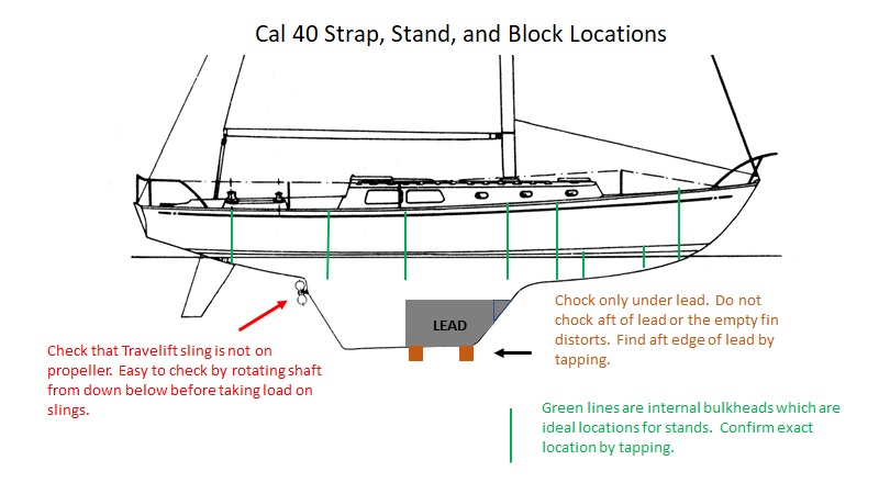
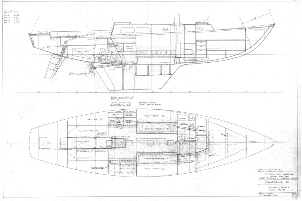
Hauling and blocking a Cal40
Cal40’s are loved by boatyards because they are so easy to handle. With their relatively long keel they are trivial to block and are perfectly stable on the hard.
On the other hand, if you take the boat to yards that are unfamiliar with Cal40’s we’ve found that it helps to give the yard boss and Travelift operator a printout so that they can avoid a few problems.
You don’t want to have the after Travelift sling lift the boat from the propeller shaft. You want the blocks to be under the lead, and you want the stands to be on bulkheads. Below is the document that we hand to the boatyard prior to being hauled.
Autopilot
We have an Alpha Spectra autopilot, built by Baron Dickey. I don’t believe that Alpha Spectra pilots are still in production. Baron provided us with an interface board that allowed me to externally control the pilot with software running on the laptop. The software that I wrote allows the pilot to steer by constant AWA, or to steer the optimum AWA as a function of TWS based on the polars. The software also has a tack and gybe function with configurable delay, turn-rate, and overturn.
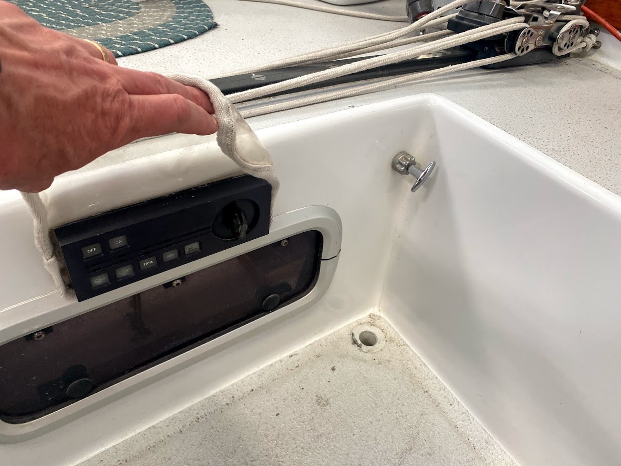
The deck controller is in the cockpit. Sally made a vinyl flap that covers it and dramatically reduces the amount of water that the controller has to deal with. You just flip up the cover to access the controller. We replaced the beautiful machined round knob on the Spectra controller with a cheap/ugly pointed plastic knob that allows you to feel which way the knob is pointed even when you have gloves on at night.
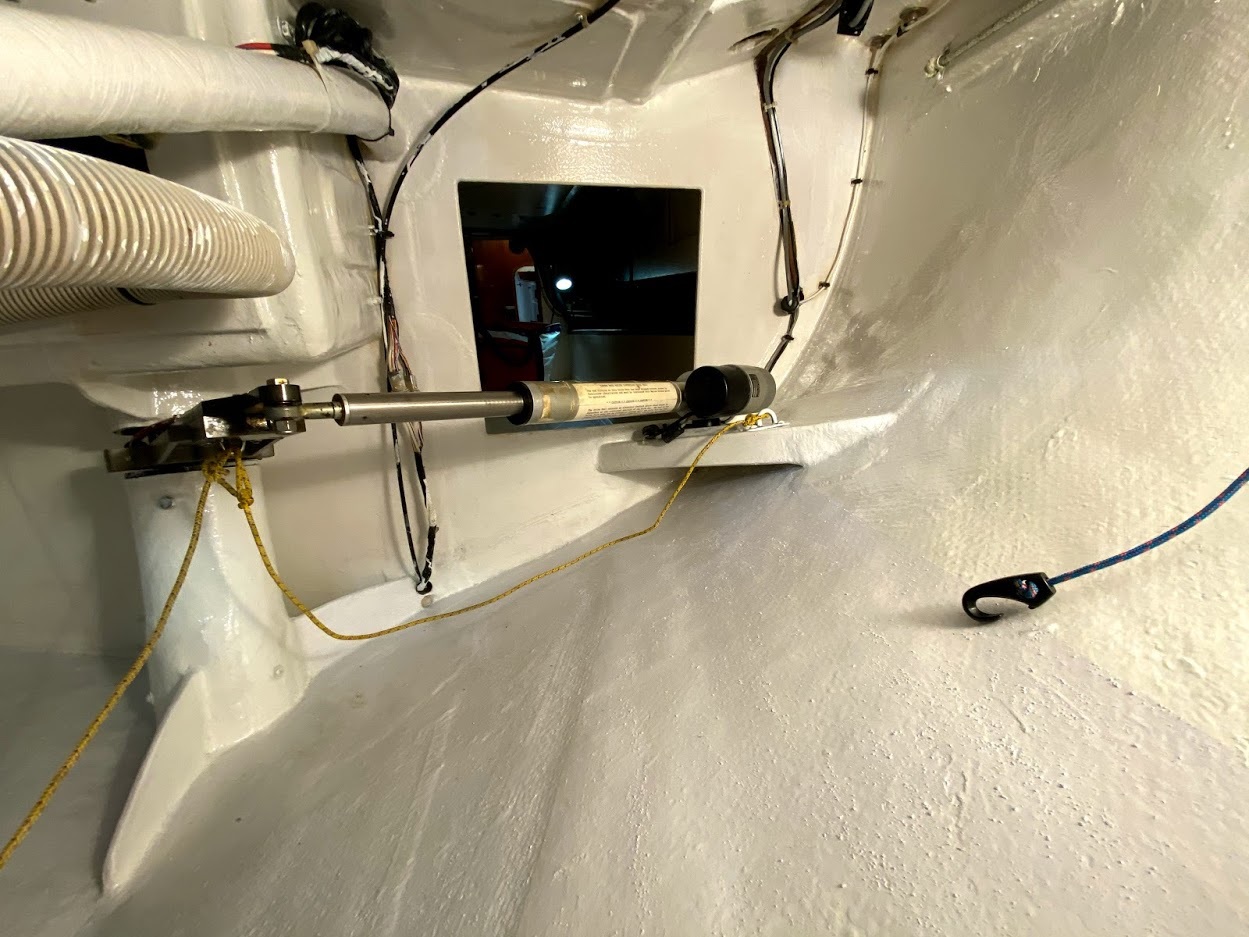
The actuator is mounted below decks. The actuator is mounted in the forward starboard corner of the lazarette on a glassed in platform. Of course the pilot-tiller is mounted at an angle so that when the rudder is on centerline the pilot tiller is perpendicular to the actuator.
The Alpha Spectra pilot has a tiller that allows you to entirely disengage the actuator with a Morse control cable. You can see the control cable in the cockpit to the right of the pilot controller.
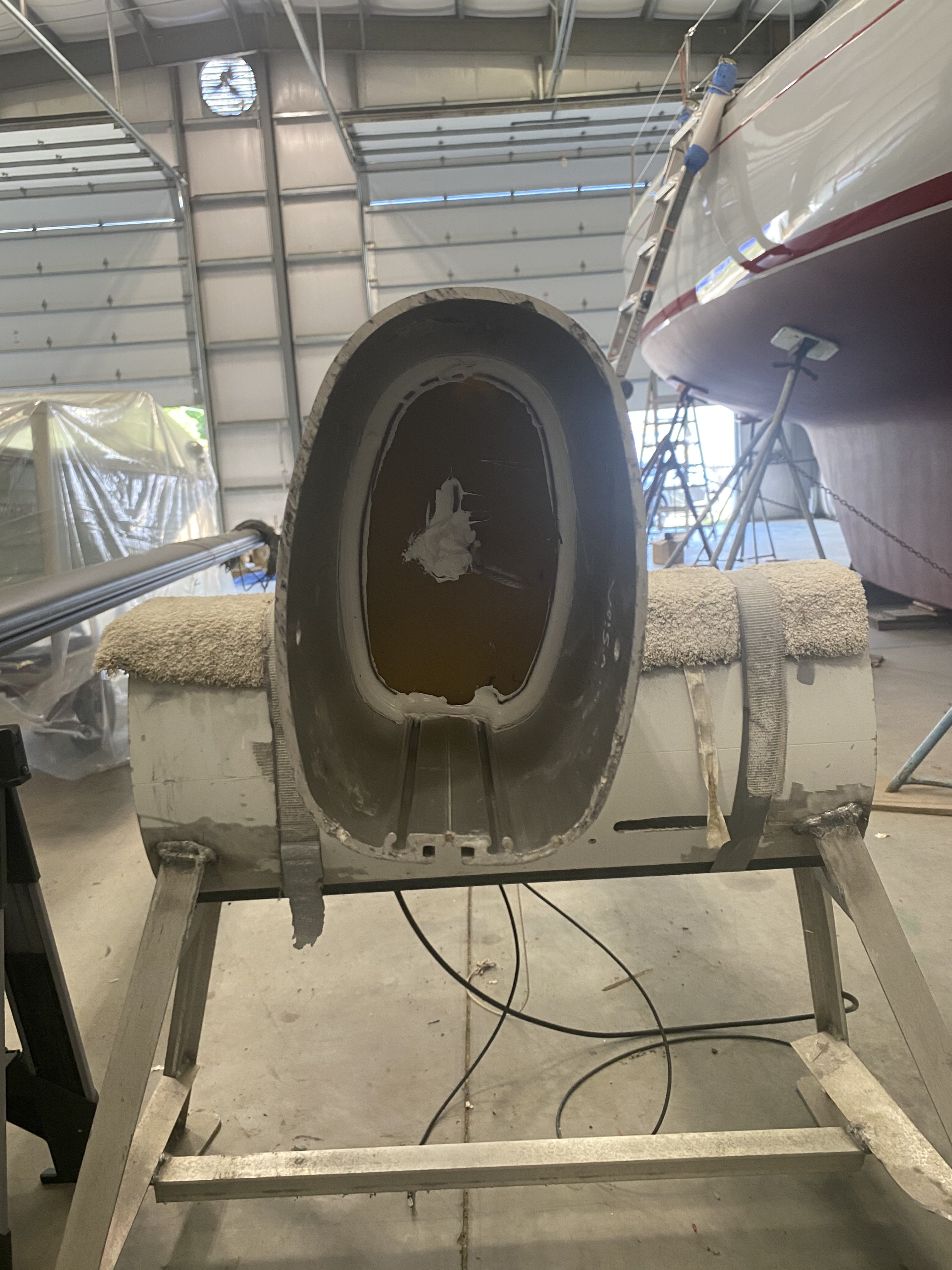
Note the gussets on the top and bottom of the rudder tube, and note that the cutout in the rudder tube is as high as possible under the cockpit floor. We use Edson stainless lower roller bearings on the rudder and have a seal at the top of the rudder tube, just under the pilot-tiller. Water has never reached that height and the underside of the seal remains dusty.
When crossing oceans single or doublehanded we carry a spare pilot, and a tiny/weightless Honda EX350 350 watt generator to reduce the likelihood that we will have to hand steer as a result of a pilot or engine problem. We’ve had to use pilot spares a couple of times but have never had to use the generator to recharge the battery.
We drop the rudder with every time we repaint the bottom to clean the lower bearing and inspect everything. The ruddershaft was built for a Santa Cruz 70 and the rudder was designed and built by Larry Tuttle of Waterrat. The rudder has the same area and post location of the original rudder but is a deeper, thinner, and has a more modern section.
Cal40 sail crossover chart
This is a sail crossover chart for ILLUSION, which is a stock, class, Cal40. Note that the true wind speed (TWS) index is vertical along the Y axis, and the true wind angle (TWA) is horizontal along the X axis.
Also note that if you look carefully you can see lines showing the apparent wind speed (AWS) and apparent wind angle (AWA) as dashed lines plotted within the graph. Of course the polar data for ILLUSION was used to compute the AWA and AWS numbers.
The dotted lines along the left and right side are the VMG upwind and downwind conditions.
The sails have far more overlap than shown. The plotted boundaries are about in the middle of the overlap between sails. Sailors have to decide when to change based on wind-weight, wind-twist, seastate, and expected future weather.
The J1’s are conventional, deck-sweeping 155% genoas. The BR (blast reacher) is a 125% high cut which has a zipper reef to about 95% overlap with a short luff. The JT (jib topsail) is a 155% high cut. The HA (heavy air spinnaker) is a full size symmetric but with two-ply 1.5 oz nylon all except for the center where it is single-ply 1.5 oz. It has very heavy tapes. This is the spinnaker shown in the photos above of Illusion. We’ve carried it in up to 45 knots so long as the seastate is manageable.
The chart doesn’t show staysails. We nearly always carry a genoa staysail under the JT and BR and reefed BR. We carry the genoa staysail alone but still on the staysail stay, with a triple reefed main when beating above 30 knots until about 42 or so. Above that we change plans or heave to.
The A-sails are conventional modern designs.
The J3 is a 110% where the leech fits just in front of the spreaders so that it can be sheeted inboard, inside of the upper shrouds, letting the Cal40 point high.
There is no J2 because in our view Cal40’s hate J2s and can’t point with them because J2s have to sheet wide outside of the spreaders. We instead change directly from the J1 to J3.
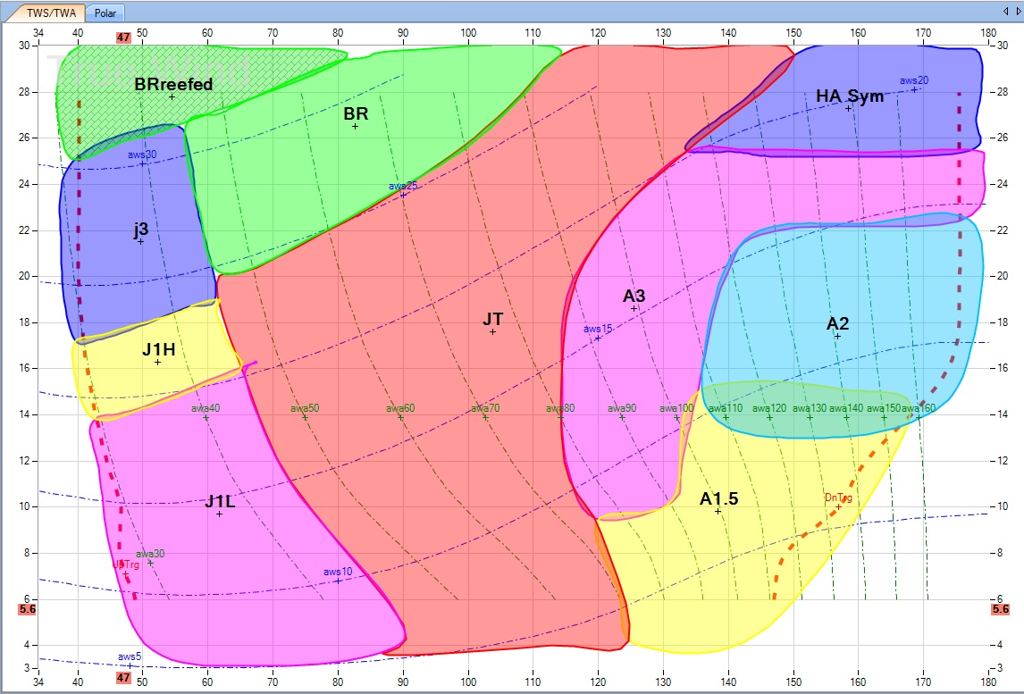
Cal40 ILLUSION sail crossover chart
Floorboards, mast drain, and how to keep water off the floorboards.
Illusion’s “teak and holly” floorboards are actually made from a Lonseal product (www.lonseal.com) made from their marine grade vinyl, which we laminated to an additional vinyl underlayment. We screwed four longitudinal and one athwartship teak strips to the original fiberglass cabin sole in the main salon, galley and nav station areas. These hold in place the six pieces of Lonseal laminate that Sally patterned to lie within the teak in the main cabin. In addition, we have separate pieces for the head, forepeak and next to the sail locker. So nine pieces in all. All are easily removeable when we need to access the hatches in the cabin sole. The pieces of Lonseal just sit between the teak strips. The Lonseal (with underlayment) is stiff enough so that even when heeled it never slides out of its place. Teak and Holly Lonseal comes in two versions. We got the non-skid version. The non-skid works great.
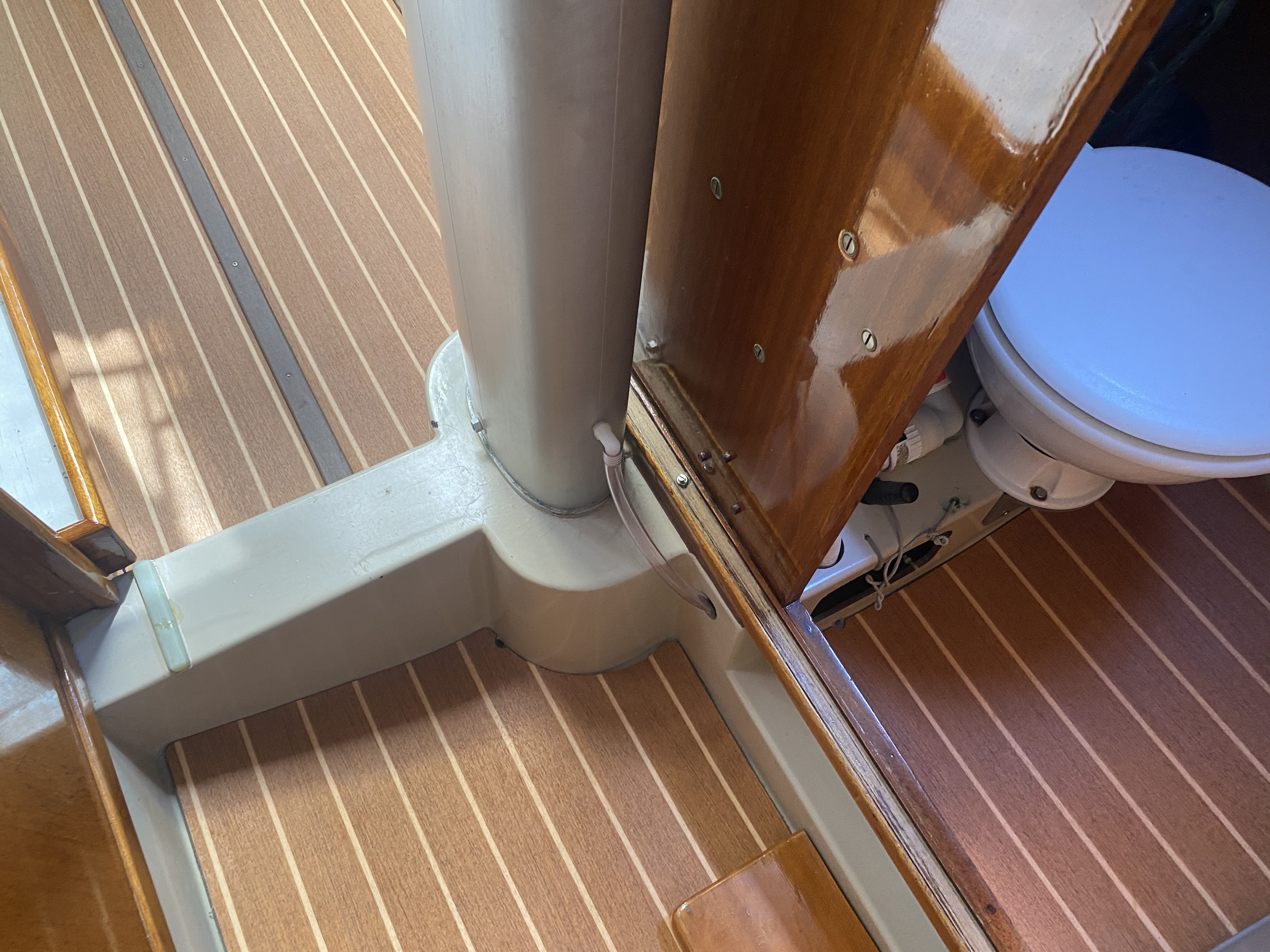
One interesting disadvantage of having the mast step be just above the cabin sole, is that the inevitable water that comes down the inside of the mast, from rain getting into the halyard slots, ends up on the floorboards, or even runs along the top of the fiberglass over the I-beam and gets into the area under the starboard settee.
We cut a piece of G10 to fit the inside of the mast at an angle, and tapped a hole for a plastic plumbing fitting just above the G10 so that the water coming down the inside of the mast can be routed through a piece of tubing into the bilge. This also keeps the mast step dry and eliminates corrosion at the step.
Navigation Lights
Here is a paper summarizing the suitability of the navigation light rules (Colregs / IRPCAS) for modern yachts. It was written by a World Sailing Working Party chaired by Rear Admiral Chris Oxenbould AO RAN (Rtd). Members of the working party included Stuart Carruthers, Will Apold, Chuck Hawley, and Stan Honey.
The paper suggests changes to the IMO Colregs, to address several areas where the rules are out-of-date and most sailboats over 20m are equipped in violation of the rules.
Note that the paper also recommends operating two sets of running lights simultaneously in certain situations (paragraph 108), and recommends the use of a masthead flashing light in certain situations (paragraph 98). These practices are good seamanship and are in compliance with the current navigation light rules.
Pacific Cup Weather Article
This is an update of an article about weather and navigation strategy for the Pacific Cup.
Volvo Ocean Race Report on High Traffic Density
Transpac Tactics, Strategy, and Weather Presentation
Here is a zoom presentation that Stan gave on Transpac Tactics, Strategy, and Weather in May 2021
Here are the powerpoint slides from the above presentation:
Hawaii Race tactics and weather 2021 zoom
Here is a closely related article.
Transpac Weather and Tactics 2021
Anecdotes in Innovation: ETAK, FoxTrax, Sportvision, LiveLine
Talk Stan gave at Stanford.
VHF coax loss calculator
Here is a spreadsheet that calculates the loss of a vhf coax in a boat, as a function of the type of coax used and the length of each segment of coax.
VHF and AIS masthead antenna installation and coax testing
This document includes some suggestions for good practices for masthead vhf-ais antenna selection and installation, and describes how coax can be easily tested.
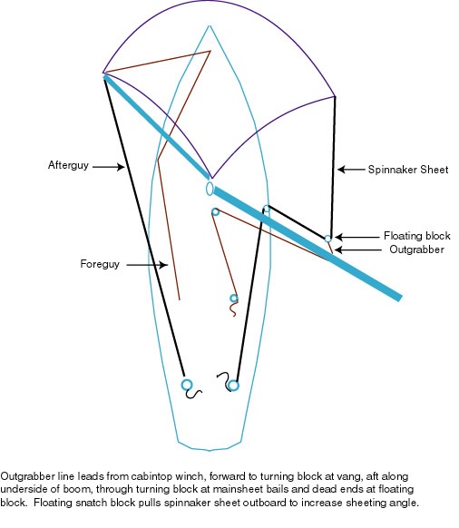
Outgrabber on spinnaker sheet
In all but light air, we sheet the spinnaker via an “outgrabber”. This is a nearly forgotten technique from the heyday of symmetrical spinnakers. It stabilizes the spinnaker when running deeply without having the leech get too tight the way it does if you just moved the spinnaker lead forward on the rail. For racing it is specifically allowed by 50.3 (b) in the Racing Rules of Sailing.
For details see:
http://www.spinnakershop.com/Out-grabber.htm
Presentations and Slides on Navigation, Preparation, and Weather
Notes on weather sources for San Francisco Bay Racing: SF Bay wx summary and tips
NYYC presentation on uses of Gribs Feb 2019 15 minutes on routing NYYC
Presentation on sailing and navigation NYYC: comanche NYYC Nav TA2016 novideo
Presentation on Navigator Preparation US Sailing.
Slides from above presentation on Navigator Preparation: Navigator Preparation
Transatlantic Record on Comanche 2016
Leave a reply
Here are some powerpoint slides with background on the TA record, the 8000+ routes we ran for the previous 11 years of weather to figure it out, and some images showing our actual weather and track. Note how small our patch of wind was late on 25 July and early on the 26 July. We were lucky.
head plumbing, backup bilge pump, shower drain pump, holding tank pump
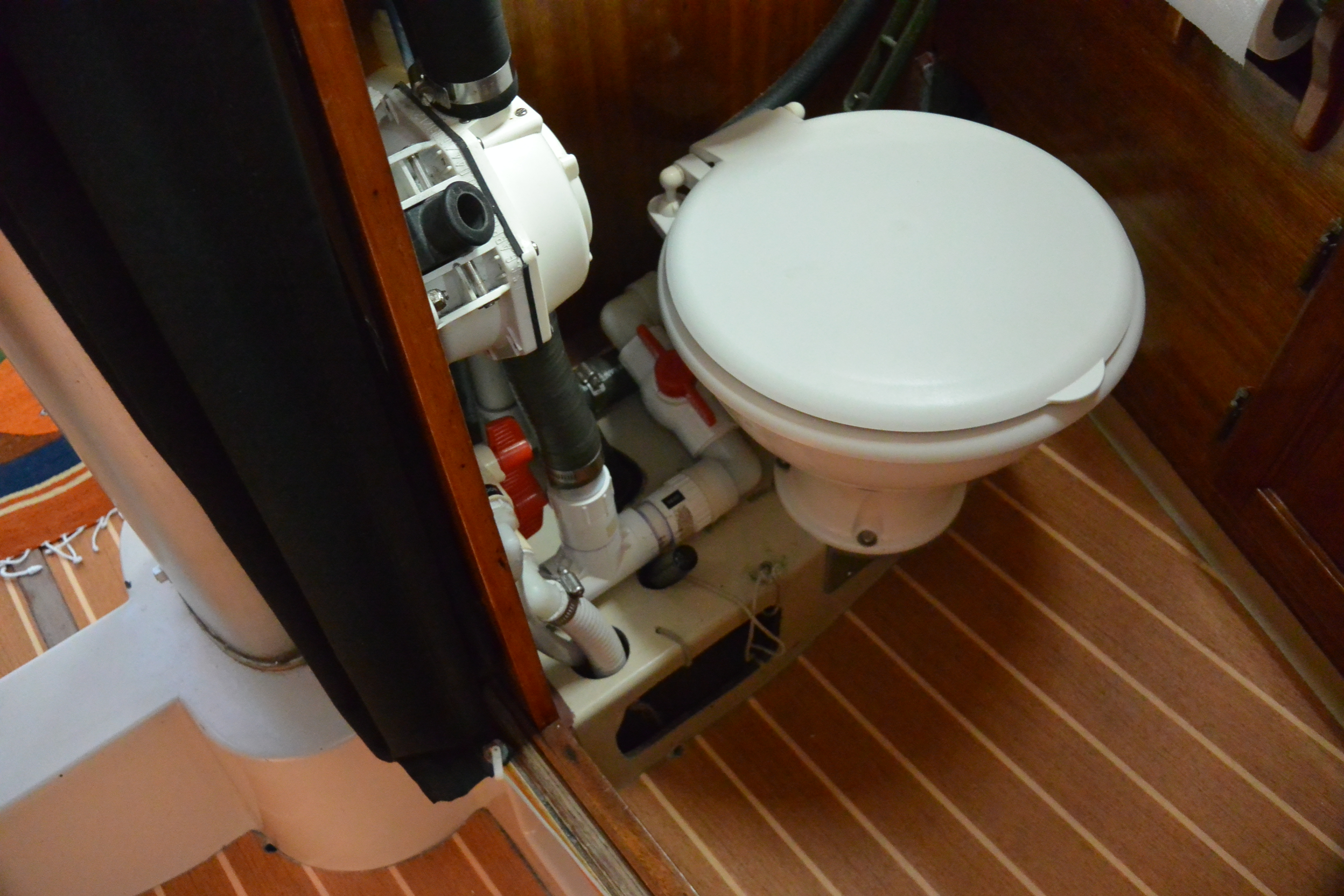
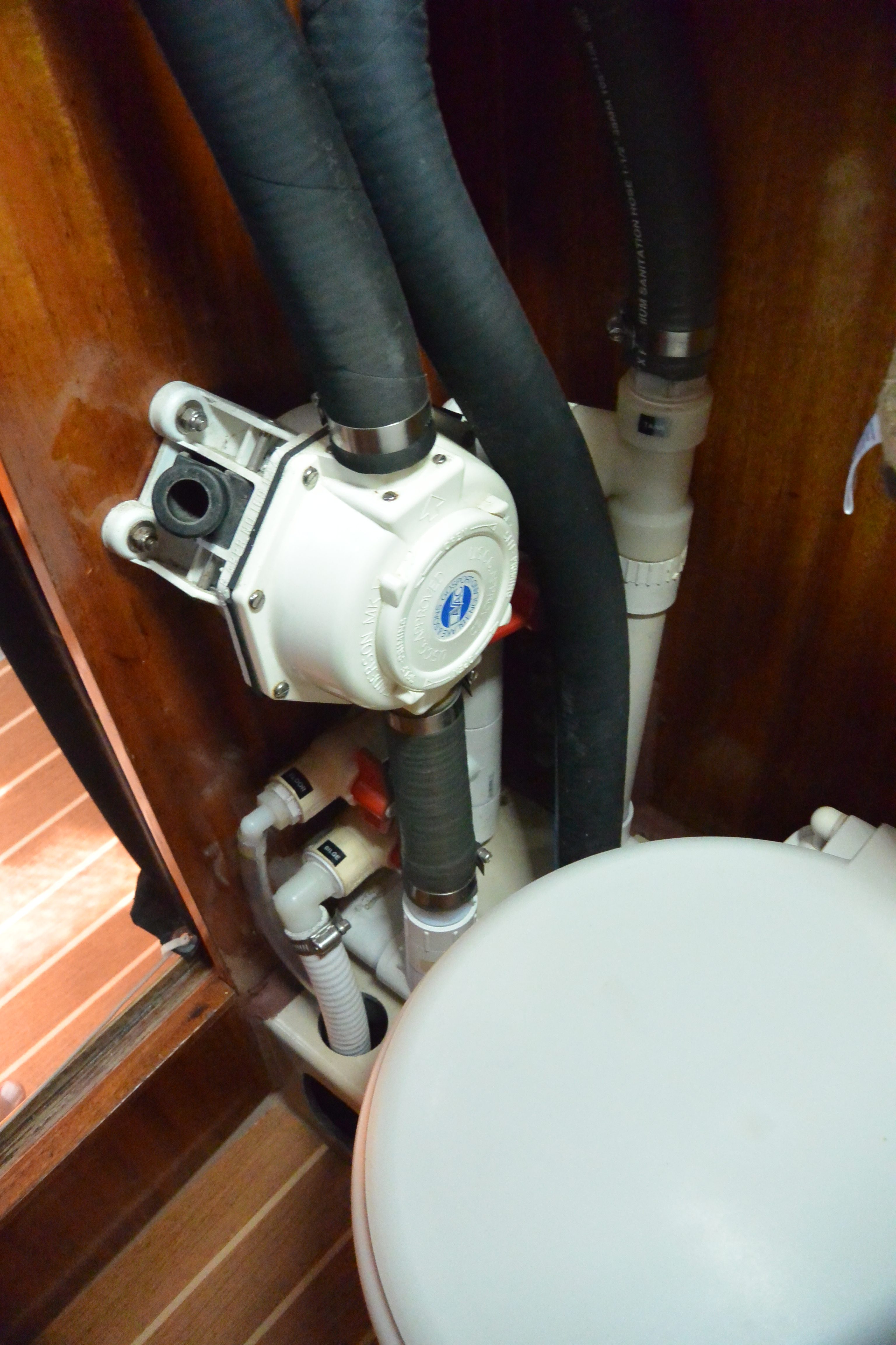
We use a Lavac head, which we’ve found to be trouble free. The Lavac head uses a standard Henderson diaphragm pump. We added some PVC plumbing and valves on the input side of the diaphragm pump so that we can also use it as a backup bilge pump, to pump out the floor of the head if we use the hand-shower, or to empty the holding tank.
The head sink is tee’d into the intake plumbing of the Lavac head, so drains into the head.
The saltwater intake for the Lavac head is plumbed into one of the cockpit scuppers, thus eliminating a thru hull.
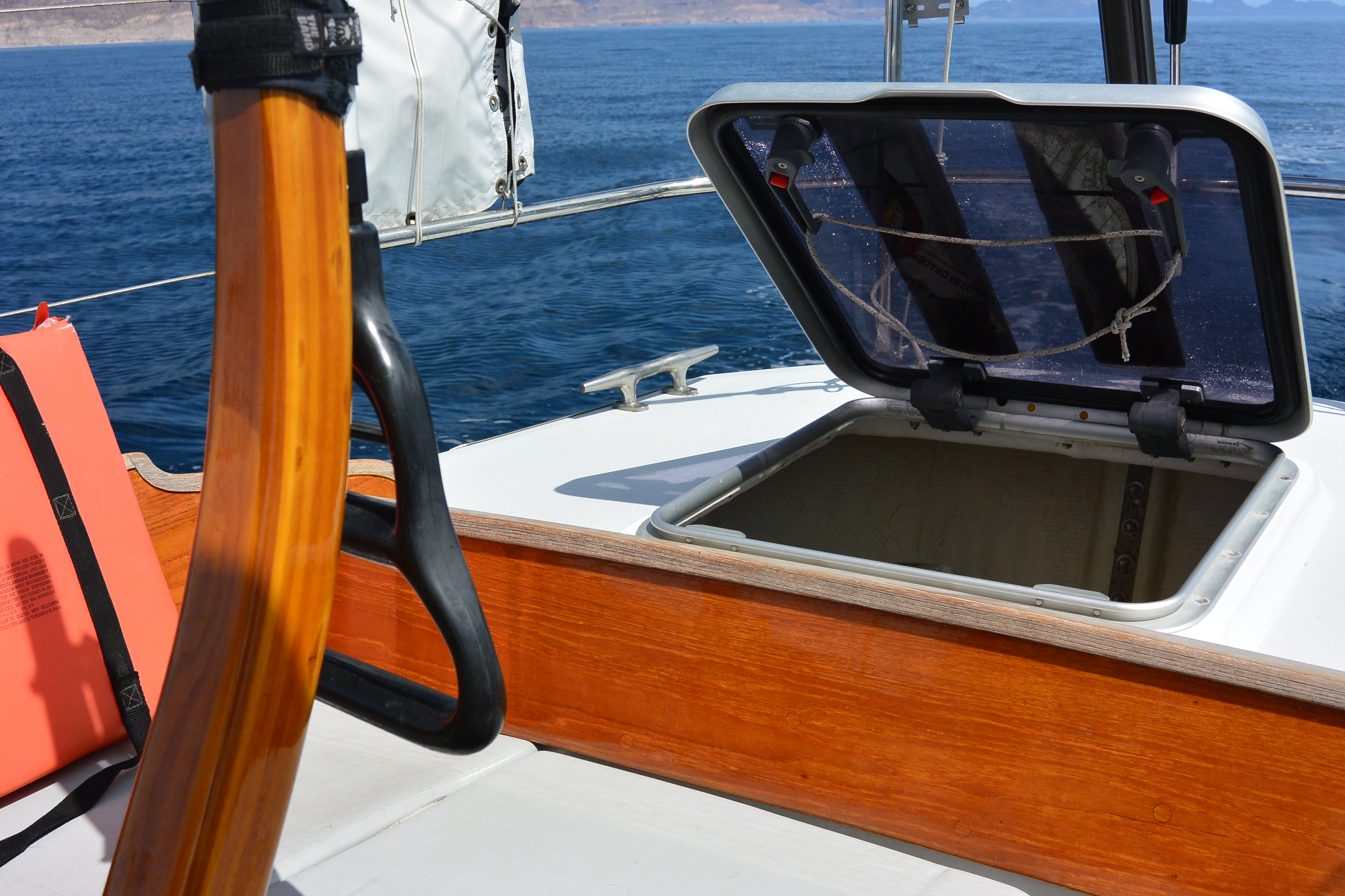
hatch leaks, foredeck and lazarette
We cut out the original Cal 40 hatches and glassed in short pedestals that are about 2 inches high at the outboard edges and absolutely flat on the top. We then installed Lewmar hatches on the short pedestals. They have been perfect and leak free for 28 years. We lubricate and clean the rubber seals every few years with some silicone grease.
varnish longevity on cockpit coamings
The varnish on the top edge of the cockpit coamings on Cal40’s never lasts long because folks sit on it, step on it, drag lines over it, and hit it with winch handles.
We borrowed an idea from Lin and Larry Pardey and put a top piece of brushed teak on the top of the coamings. The bit of brushed teak on the top is slightly wider than the coamings, which makes it more comfortable to sit on. It also makes it easier to not get varnish on it because the proud edge of the brushed teak holds the edge of the varnish brush when you’re varnishing the coamings.
That bit of brushed teak needs no maintenance, the color looks fine with the varnish surface next to it, and it saves tons of wear, tear, and work.
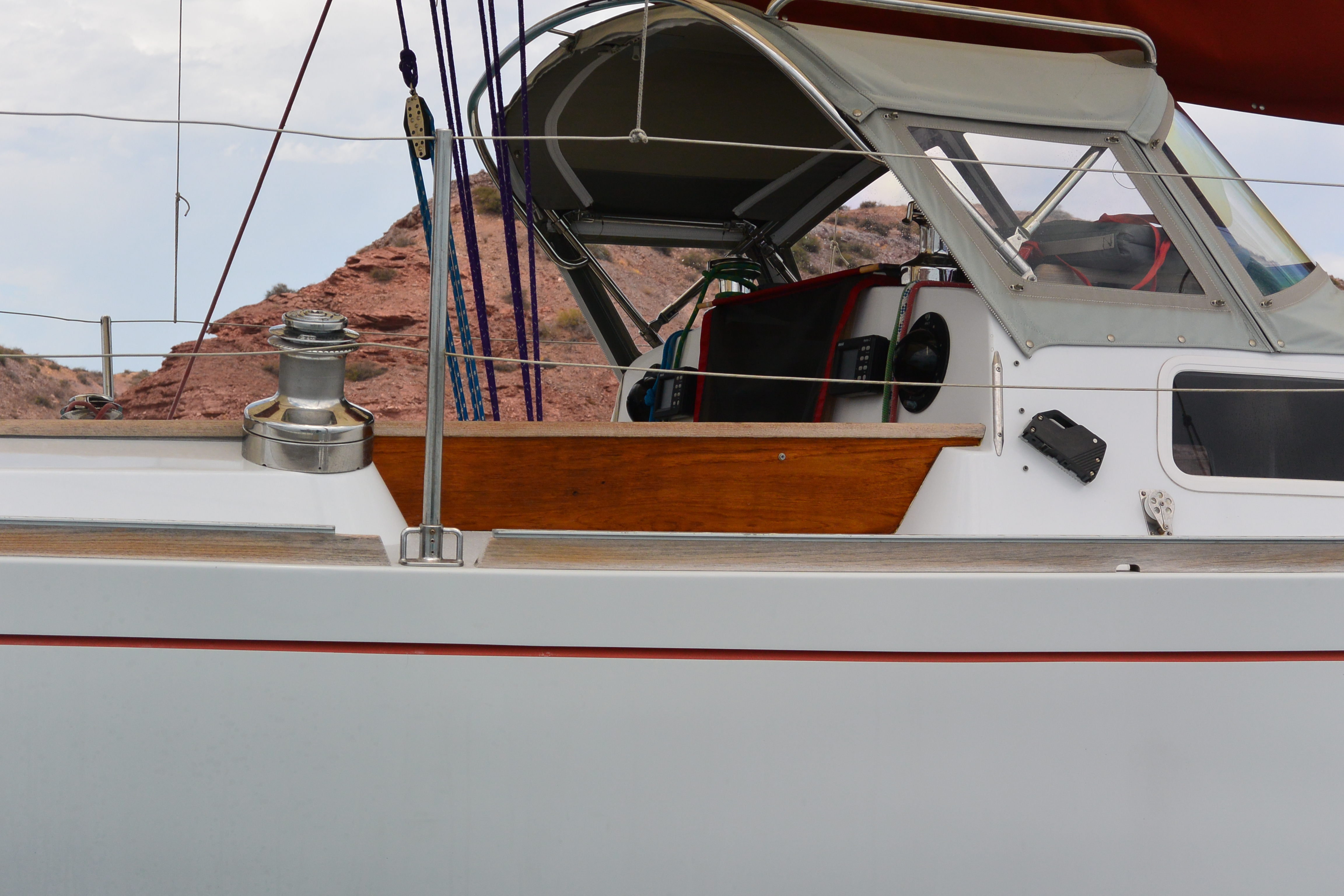
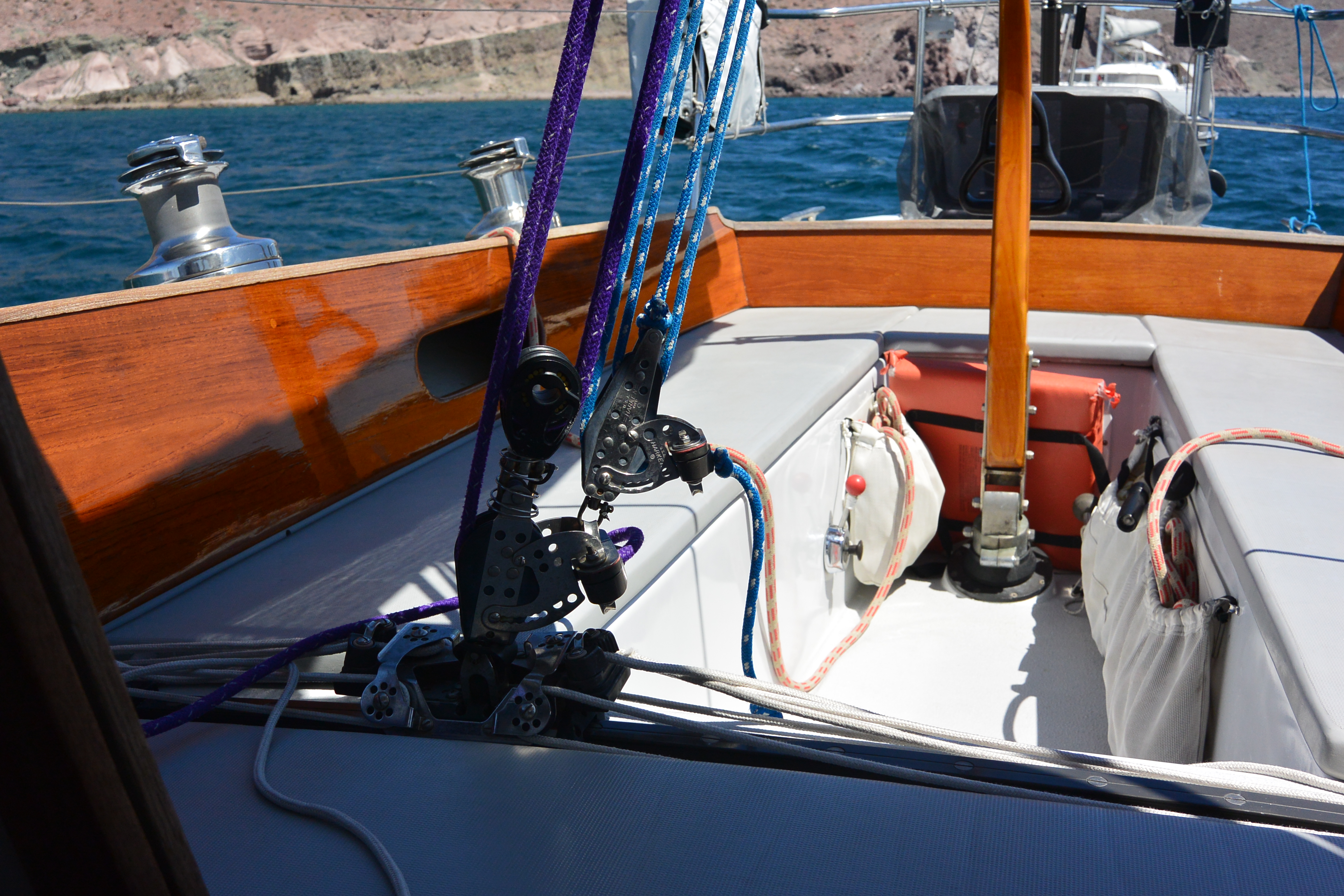
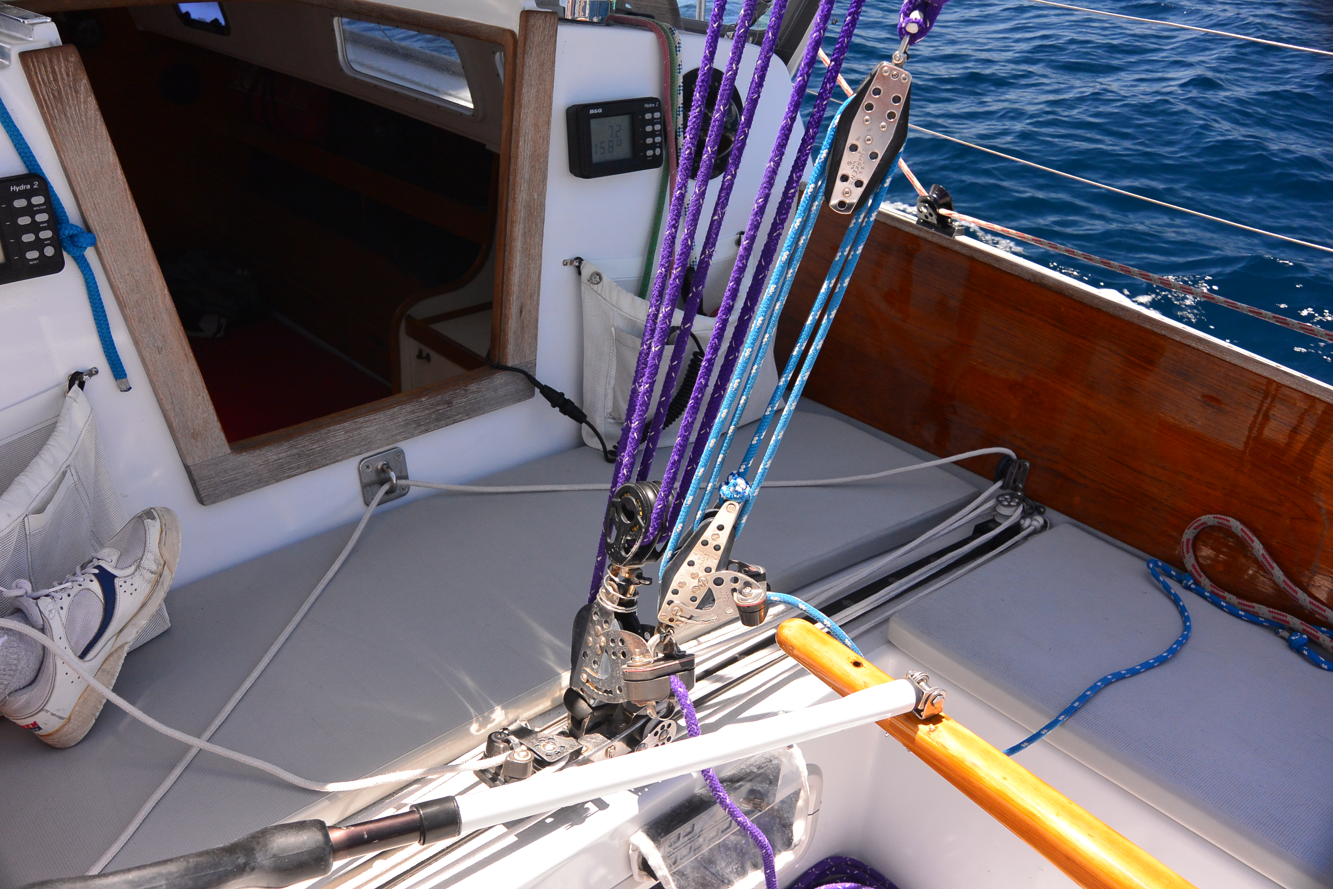
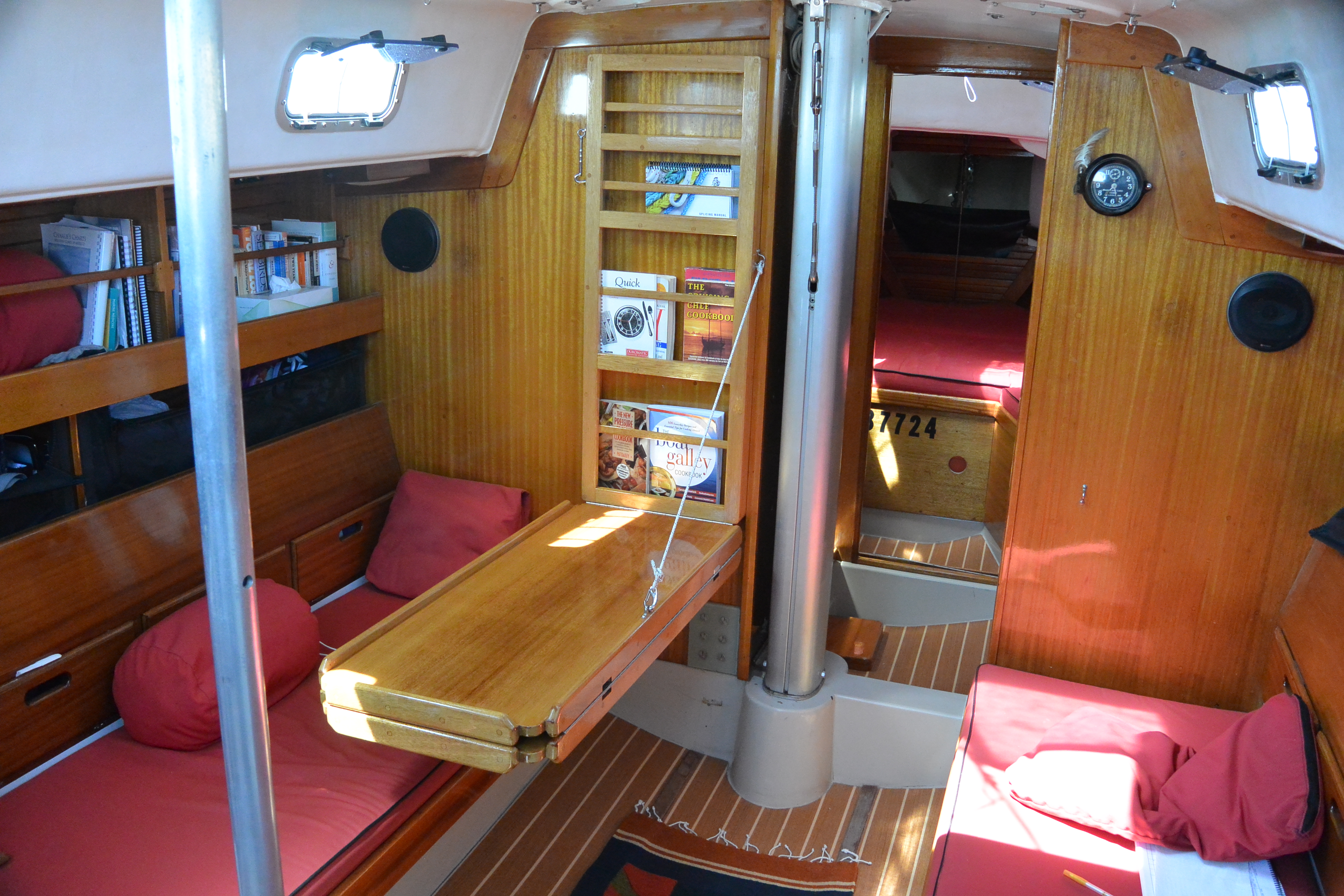
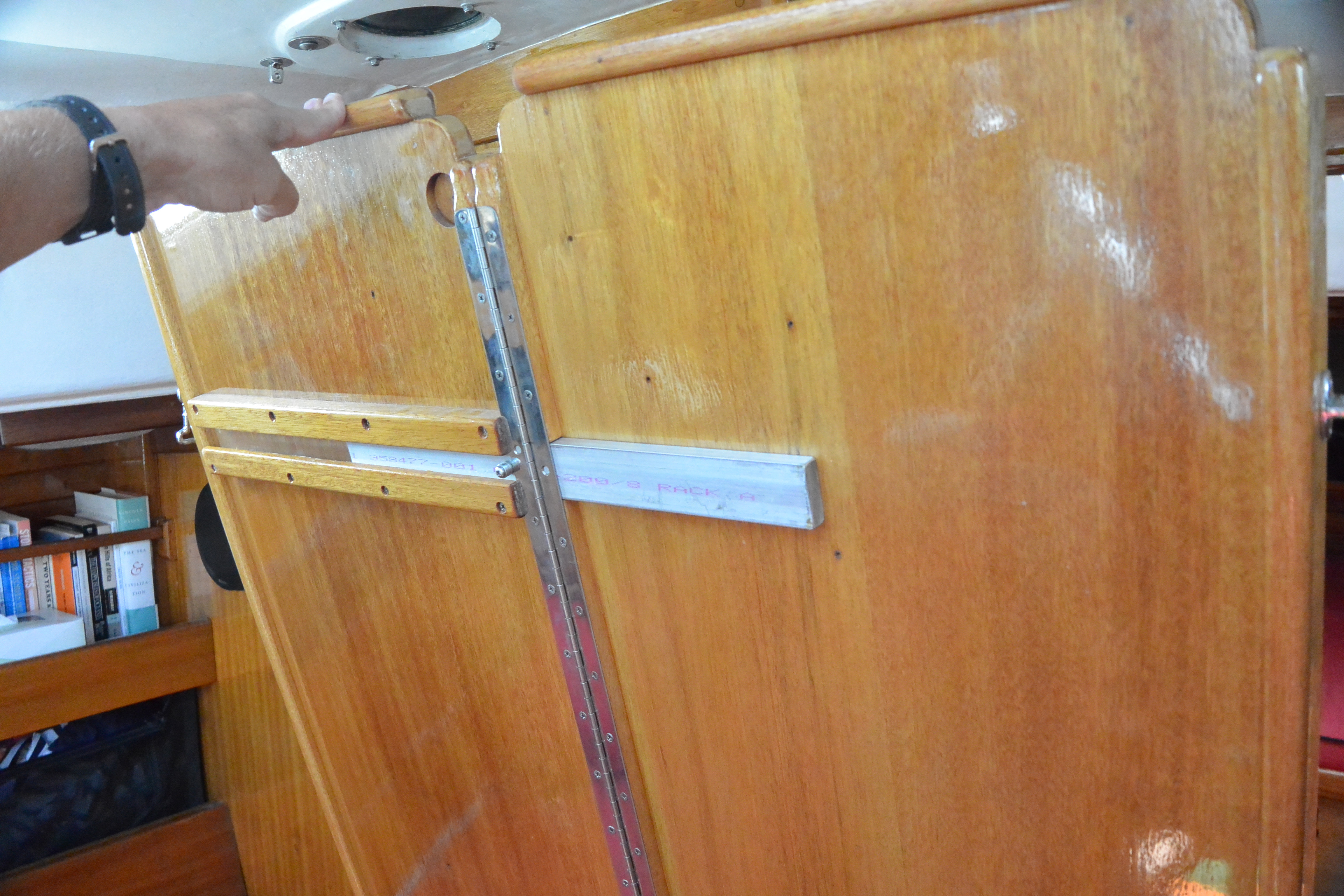
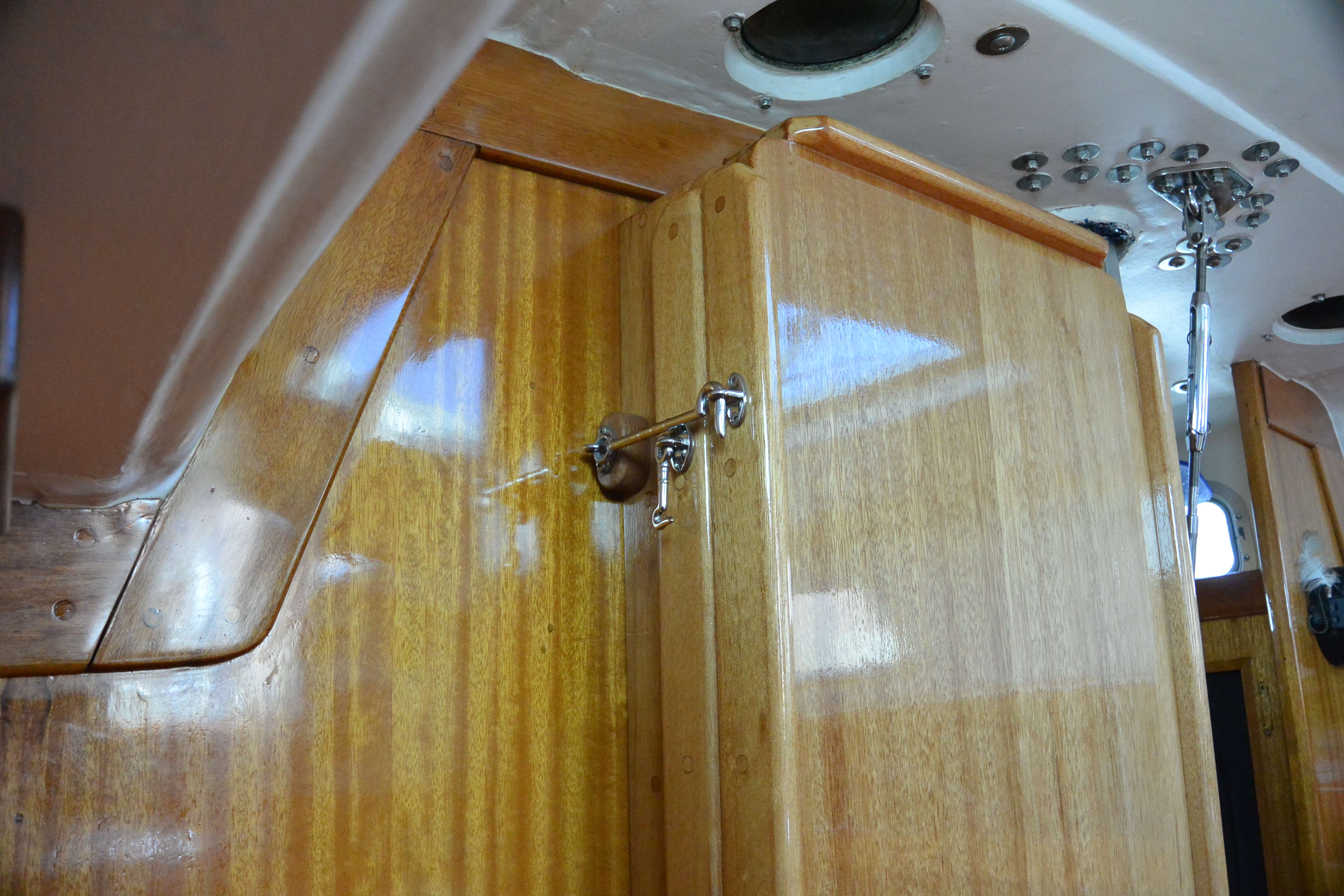
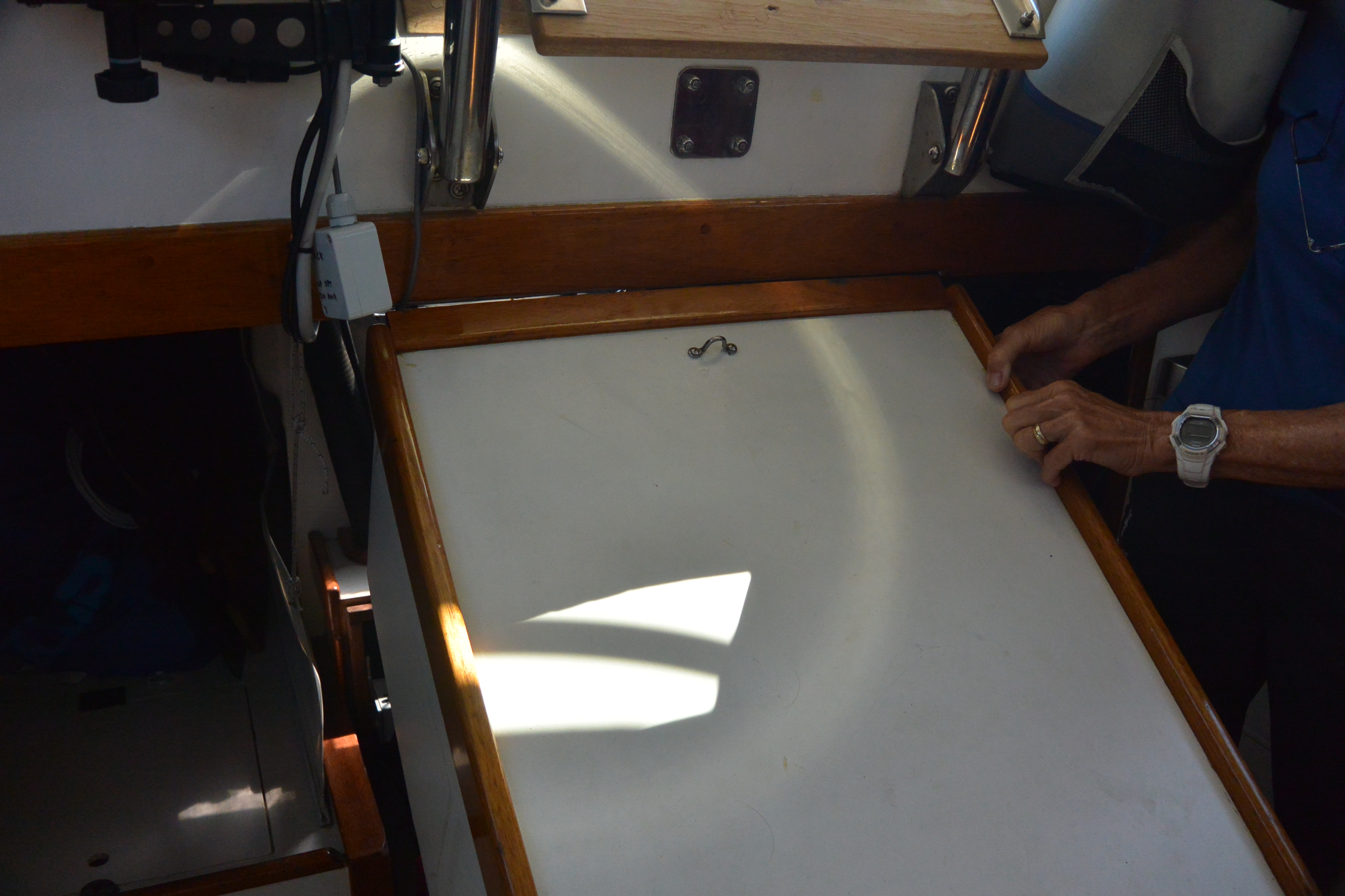
table for cruising
Bob Pearce built this table for us. It is removable for racing. It is terrific for cruising. The normal Cal 40 table tended to be in the way.
It folds up out of the way against the main bulkhead. It can be used either in a single width mode or doublewide. It is held up by a spectra line.
If Sally sets up her sewing machine on it we have a removable foot to hold the table up because the spectra line would be in the way.


roller furlers, jib hanks, reefable solent jib.
For the 2020 Newport Bermuda Race we installed a convertible Harken roller furler. Specifically we installed a Harken MarkIV Unit 1. We did this because we wanted to have a luff groove to use 3Di #1, #3, and JT headsails for the race, for which we would not have carried the furling drum. We also converted our reefable blast reacher described below to a luff tape. Once the Newport Bermuda Race was cancelled we put the furler drum on and used our 125% blast reacher for a summer of cruising in Maine, feeling guilty the entire time for having gone to the dark side and installed a roller furler. For cruising it was great. It was especially handy for short sails between anchorages. We could quickly entirely clear the foredeck for anchoring with a quick roller furl and not have the hanked jib in its bag congesting access to the foredeck. We still carry our removable staysail stay (and runners) with our combination genoa-staysail and #4 on hanks. So given that we’re reluctant to roller reef the jib in wind, we’ve got a gap in sail area between the 125 blast reacher and the #4 on the staysail stay. We left the second tack, second clew, and the zippers on the 125% blast reacher so we could reef it as described below but of course once reefed that way we could not roller furl it. We’d have to either drop it or shake the reef and roller furl it to get rid of it. The post below described what we have done for the first 30 years that we sailed ILLUSION.
We used hanks on Illusion. We like the ability to change headsails easily. Shorthanded it is also nice to be able to just run the jib halyard and not worry about anything going wrong. This is a helpful ability either in a squall, or in a spinnaker set. When you’ve got time you can pull the jib out of the bow wave and onto the deck.
In the old days when Cal 40’s were used for the Congressional Cup, with full crews and hanks, we did the same thing. At the weather mark the mastman would just run the jib halyard and let the jib just sit on the bow wave. The first crewman available after the set would later pull the jib out of the bow wave, over the lifelines and onto the deck.
Racing Illusion singlehanded on Farallon Races I would always gain on my competitors when we passed Point Blunt and had to change from our #1’s to #3’s. I’d do a bald-headed change, but I’d already have the new sail hanked on under the old one, so I’d just have to drop the old sail, tie it to the deck, unhank it, move the halyard, and hoist the new sail. At no point in the process was there any risk of losing control of a sail or having a sail blow out of the luff groove. Meanwhile the guys trying to change a luff groove genoa by themselves were having a very difficult time, and the guys with roller furlers had a hopeless sail shape once furled and were out of the race.
We don’t see many boats using hanks any more in the cruising fleet, but it works great for us.
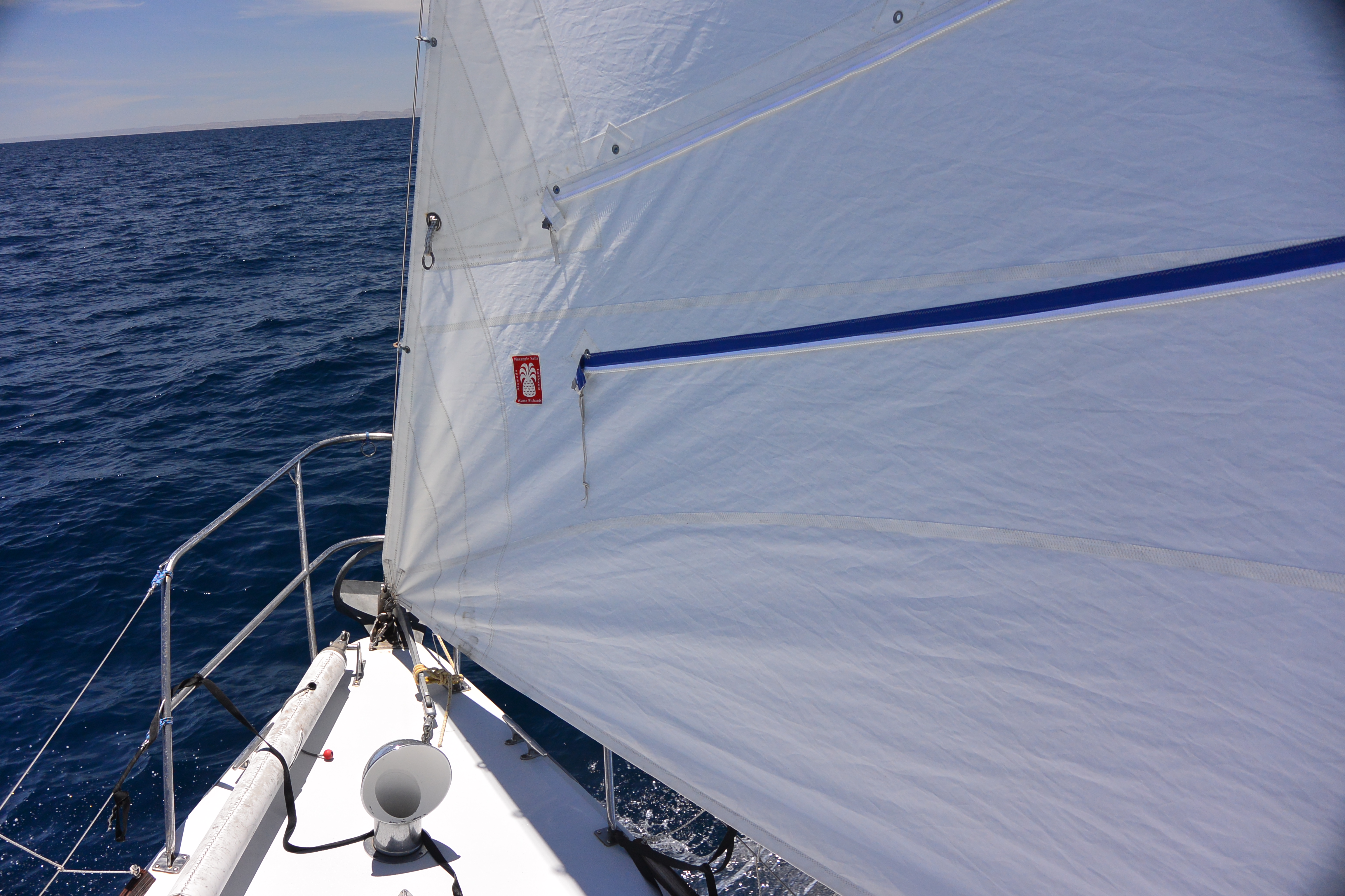
On Illusion for cruising and deliveries we use a 125% reefable solent jib, and keep it on deck in a jib bag when at anchor. We didn’t invent this sail. I first ran across this idea when I delivered the Cal 40 Whisper back from Hawaii after the 1975 Transpac. I credit the Brauch’s for inventing it although Whisper’s solent jib used reefpoints instead of a zipper and tended to hold water in the reef.
The jib has two tacks and two clews.
To reef the jib you temporarily drop it on deck, roll the foot up, run the very heavy zipper which encloses the rolled up foot, change to the new tack and clew, and rehoist. The jib goes from a 120 to a short hoist 100. Having the reefed foot enclosed in the zippered pocket keeps any water from accumulating in the folds of the reef, which can happen if you use reef points.
There are two sets of zippers, blue and white, that are sewn on back to back. If on port tack it is easiest to use the white zippers. On starboard tack the blue zippers are easier to use. Our procedure is to drop the traveller, ease the mainsheet, slow down, bear off a bit, drop the jib entirely, tie the head down to the pulpit, pull the sail inside the lifelines, attach the second tack, put the sheet onto the second clew, pull the new foot sort of tight by temporarily tying a hitch of jib sheet around the shrouds, take the old clew up and forward and tie it to a sail tie that is in the right place. Then roll the foot up and away from you until the two (identically colored) zippers meet, zip the zipper, tie the zipper car so that it won’t move, untie the sheet hitch at the shrouds, untie the halyard hitch at the pulpit, and hoist away. It takes less time that it sounds, is easy, avoids an extra jib, and avoids an unused jib on deck or a wet unused jib down below. It preserves all of the seamanship advantages of hanks not the least of which is that you can drop the jib entirely at any time just by casting off the halyard and the jib stays well controlled even if riding along the top of the bow wave.
Reefing the jib has a number of advantages. The sail has a perfect shape both when reefed and unreefed. We are able to carry one fewer sail.
For racing upwind, however, we use a lowcut conventional 155% LP #1, and a #3 that is as large as possible but still have the leech fit in front of the spreaders so that we can sheet it inboard. We do use the highcut, reefable 125% as a blast reacher in Hawaii Races, as well as cruising and deliveries.
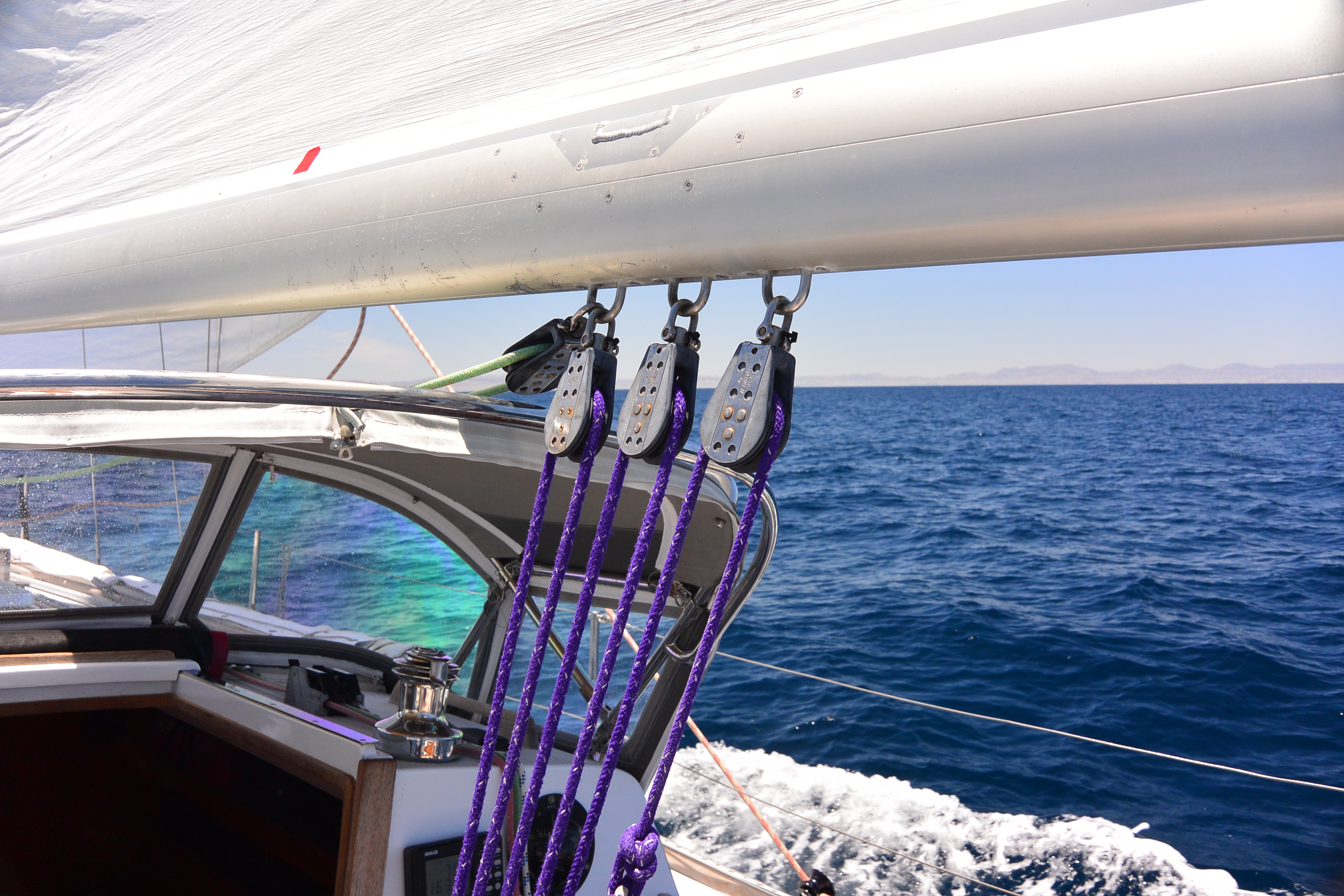
mainsheet and traveler
Illusion has her traveler on the aft edge of the bridge deck, which is unusual.
Interestingly, George Griffith mentioned that this is exactly where he intended for the traveler to go on Cal 40’s, but after sailing Persephone, he found that with a full crew it got too crowded in the front of the cockpit.
Also, he originally intended the primary genoa winch to be the after winch, which is why the aft end of the winch islands is wider, but he quickly discovered that Cal 40’s don’t like weight aft. So nearly all boats moved the traveler aft, and the primaries forward.
On Illusion, however, we mostly race doublehanded, so we don’t have a crowding problem. We have a 6:1 with 24:1 fine tune mainsheet that can be trimmed directly from the ratchet block and doesn’t need a winch. When doublehanded or singlehanded it is terrific to be able to steer, and adjust both main and traveler. Also, having the traveler farther forward allows it to be effectively used at somewhat wider angles close reaching.
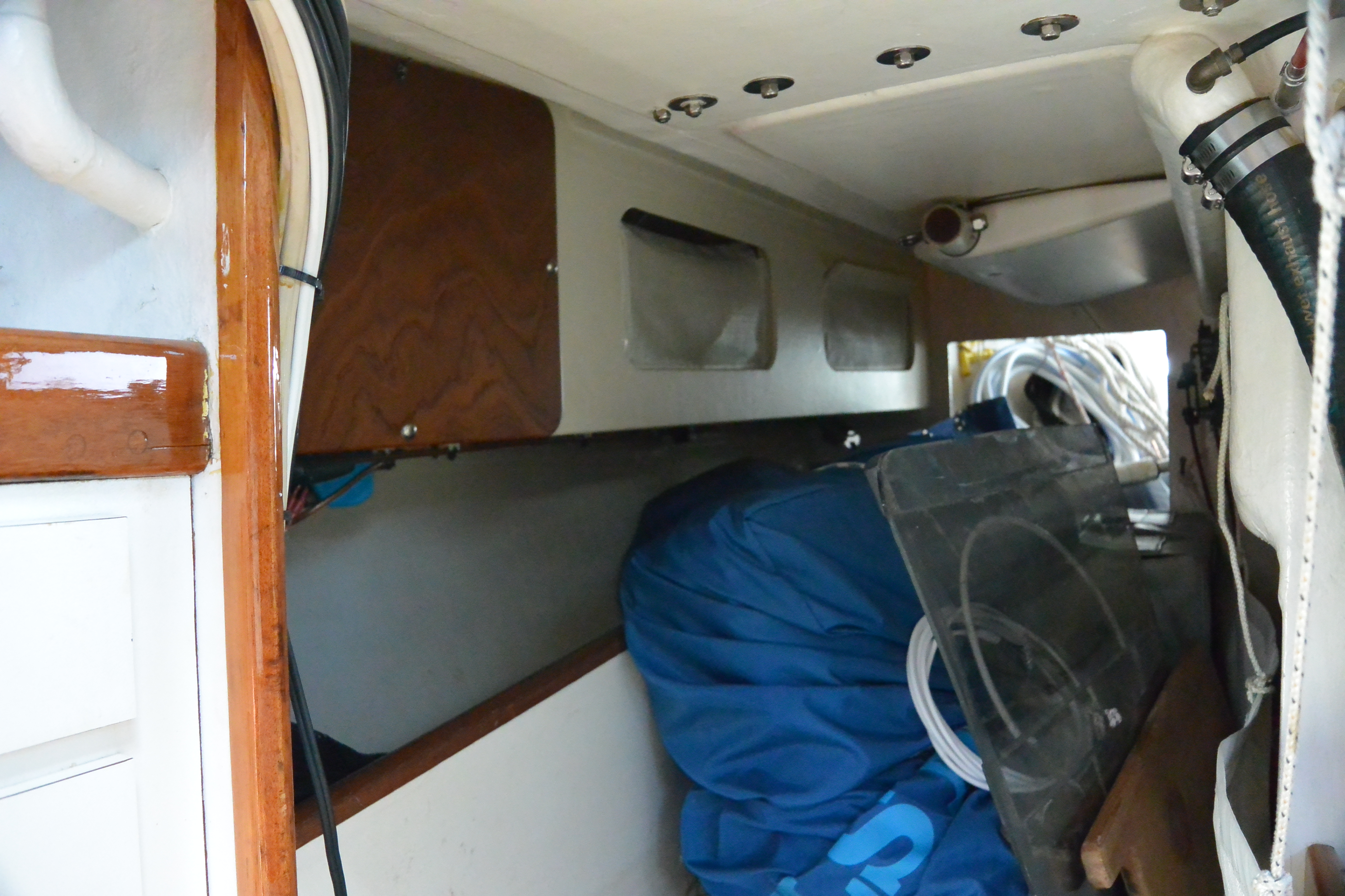
stiffening the hull, extra storage, propane locker
Illusion’s pilot berths have been replaced with shelves, and the faces that holds the drawers adjacent to the settees have been moved outboard about 8 inches. The settees are fixed and do not slide.
Given that we didn’t need the space for the settees to slide under the drawers, we removed the drawers and used the old drawer faces as hinged cabinet doors. There is now a longitudinal bulkhead that extends from the drawer faces down to the hull, and between each cabinet there is a small athwartship bulkhead that separates the cabinets and is also glassed to the hull. This has made the middle of the boat very rigid.
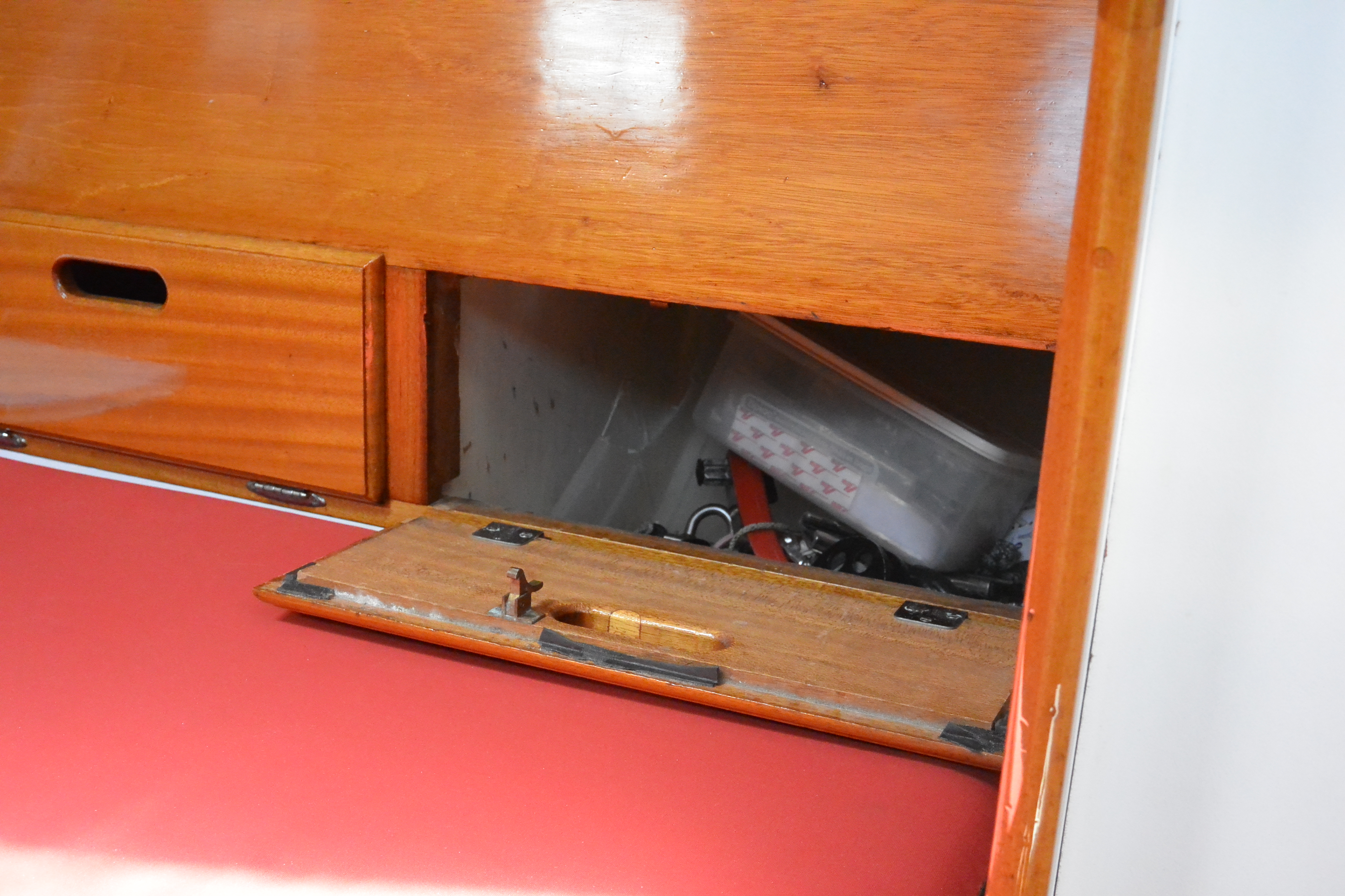
Under the gunnel outboard of the quarterberths we installed storage lockers. Those panels also have stiffened the boat. the forward most locker is a vented propane locker that has a removable, gasketed panel (varnished) that is used to remove the tanks to fill them. We carry two 20 lb, aluminum, horizontal, propane tanks, one on each side. The tank compartments are vented to the thruhull that is above the water line just below the propane locker that is also used to drain the cockpit seats. We have an “air release valve” in the hose from the propane locker to the scupper to keep seawater out of the propane locker when the boat is heeled far over on a windy reach. https://plastomatic.com/arv.html We have a removable propane Cozy cabin heater which explains why we can carry two tanks,
Strictly speaking, this propane installation does not meet ABYC because propane lockers are not supposed to open into the interior of a boat. Whenever Illusion has been surveyed, however, every surveyor has noted that the installation is not precisely compliant with ABYC, but it is safe, the lockers are airtight and vented outboard, and that they would have done exactly the same thing if they owned the boat. We’ve never had an insurance company complain given that the survey says it is a safe and sensible solution.
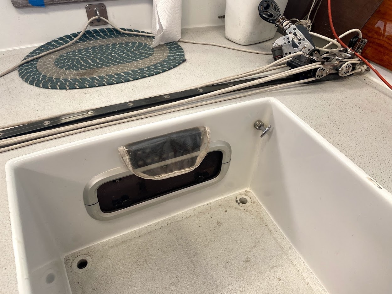
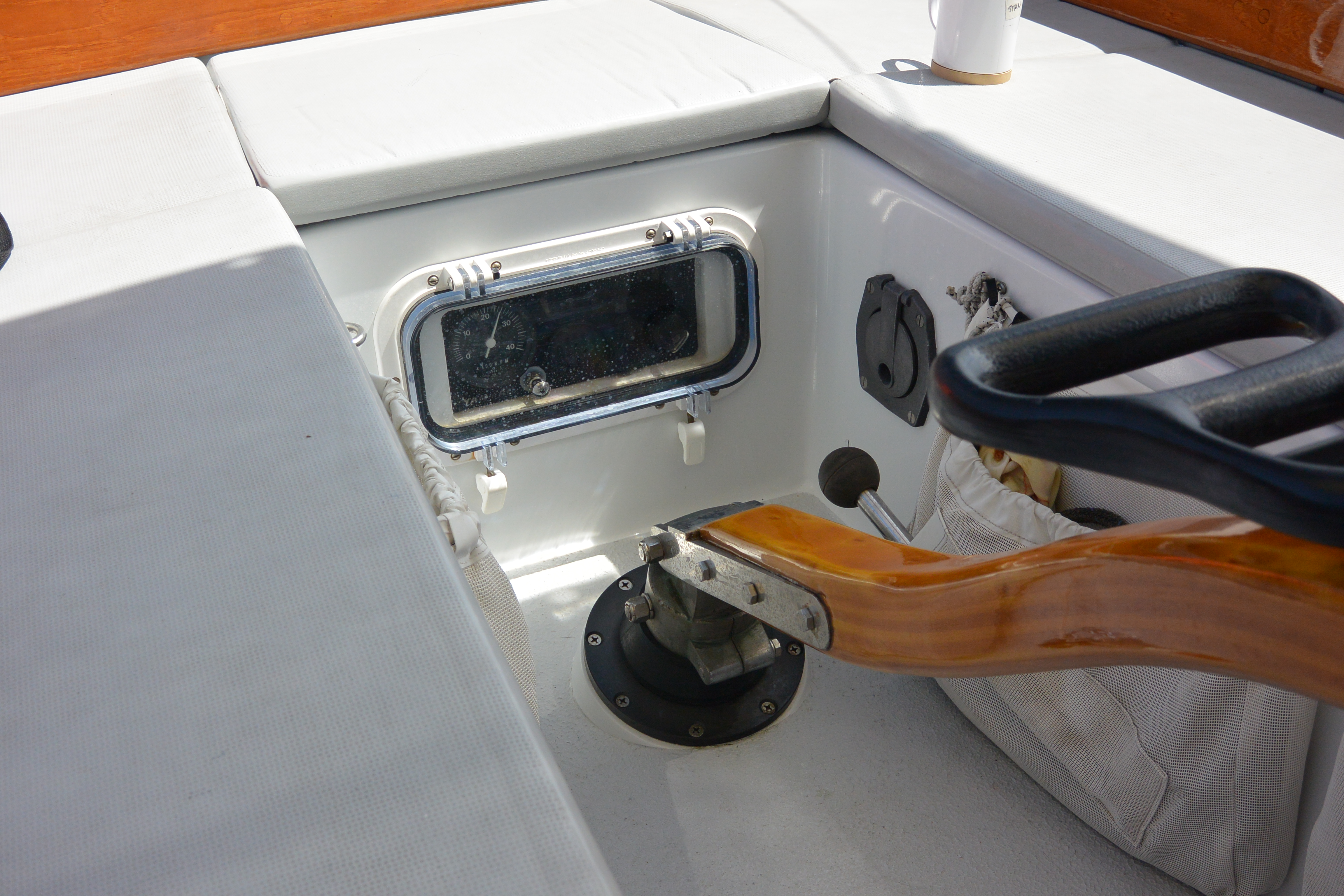
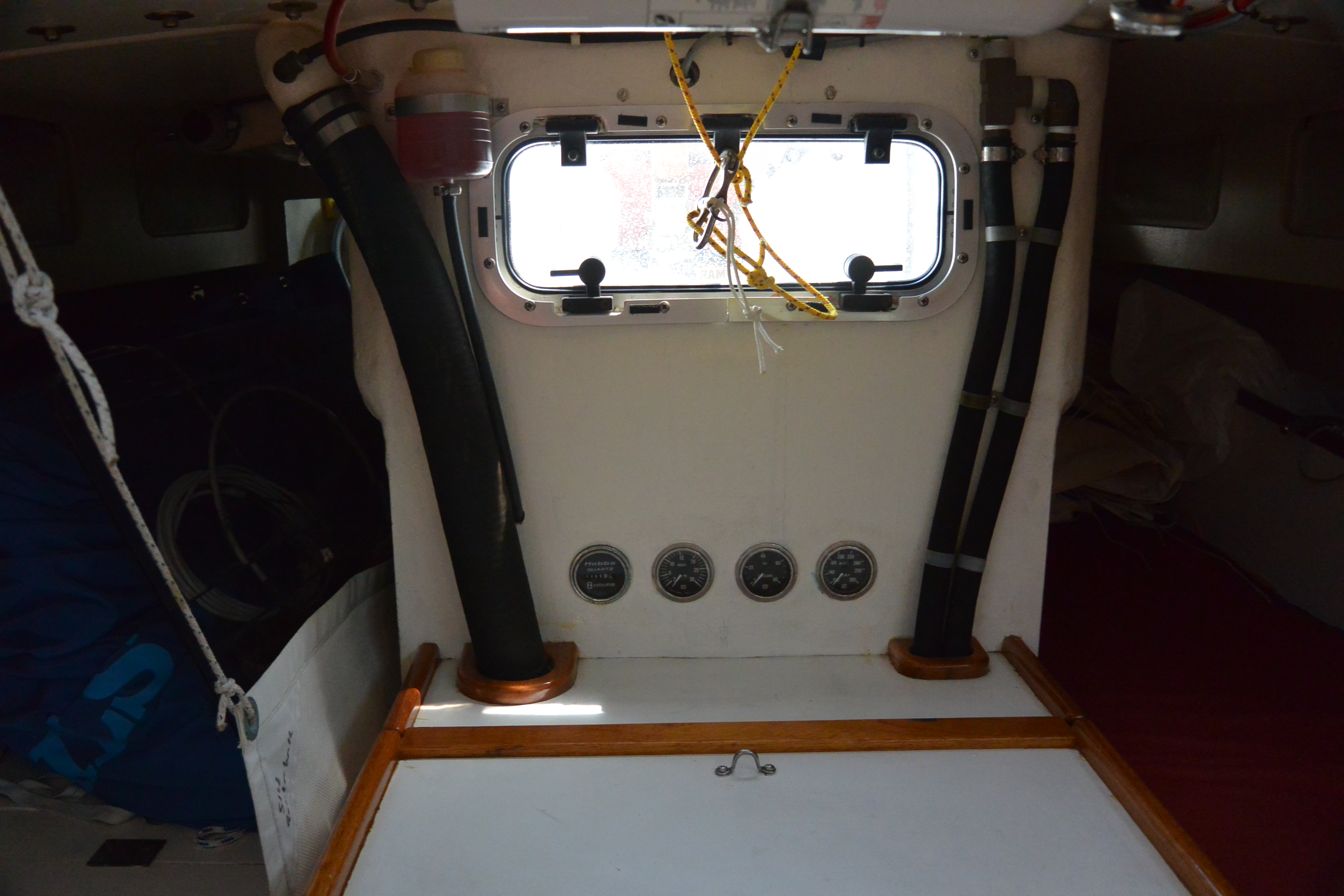
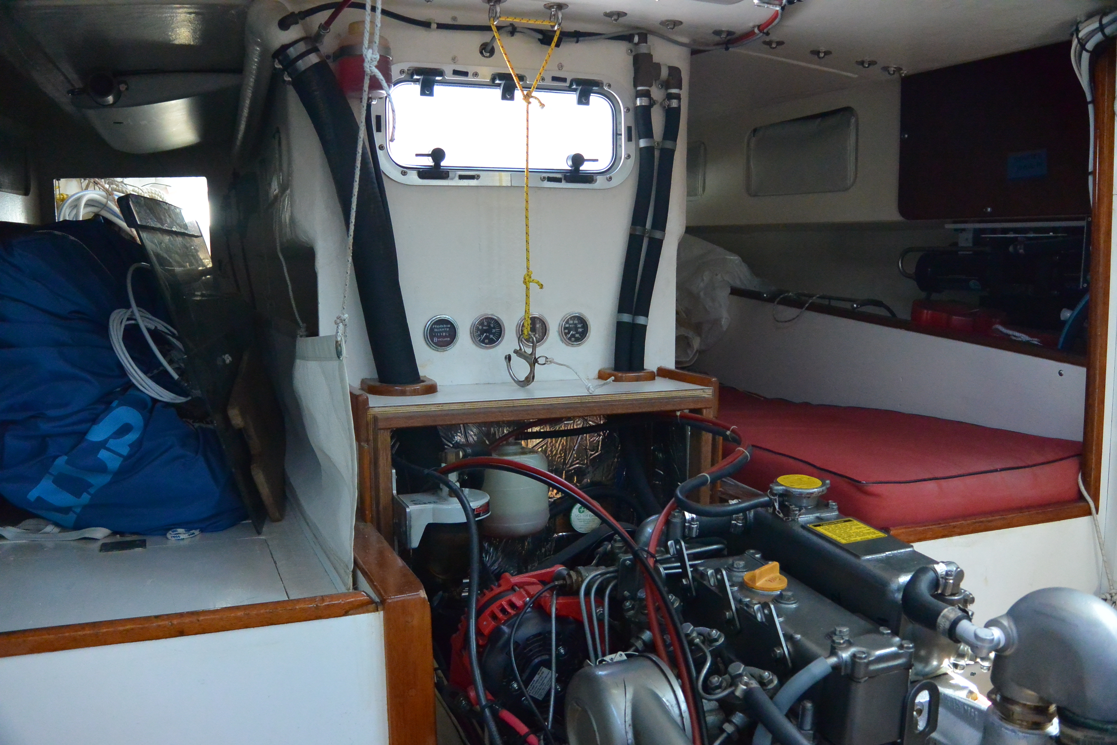
engine controls
We wanted the porthole in the forward end of the cockpit well to be usable for light and ventilation, so we put the engine controls behind a Beckson porthole in the aft end of the cockpit well. The Beckson porthole allows the engine controls to be entirely waterproof in heavy going when filling the cockpit with water. We found that by using a barrel nut as the knob, we could even fit the engine kill cable in the panel, behind the Beckson portlight.
The four gauges over the engine box are engine hours, water temperature, oil pressure, and fuel vacuum. With the exception of the hour meter, they are all mechanical gauges.

radar, removable
When cruising or delivering the boat we carry a removable radar. We have a modified car that just slides up the spinnaker pole track, and carries the radar scanner. The wire pulls up the mast on a leader and exits near the scanner.
The scanner is mounted on the car so that the edge of the scanner just touches the pole track. The scanner has to be rotated a bit so that the cable gland is out of the way. It is easy to configure the software to handle the twisted installation so that straight ahead on the boat is straight up on the display.
The radar display is on a pivot hear the companionway, so that the radar display can be pivoted to be viewable from either on deck or below.
When racing everything comes off, the scanner, display, and cable.

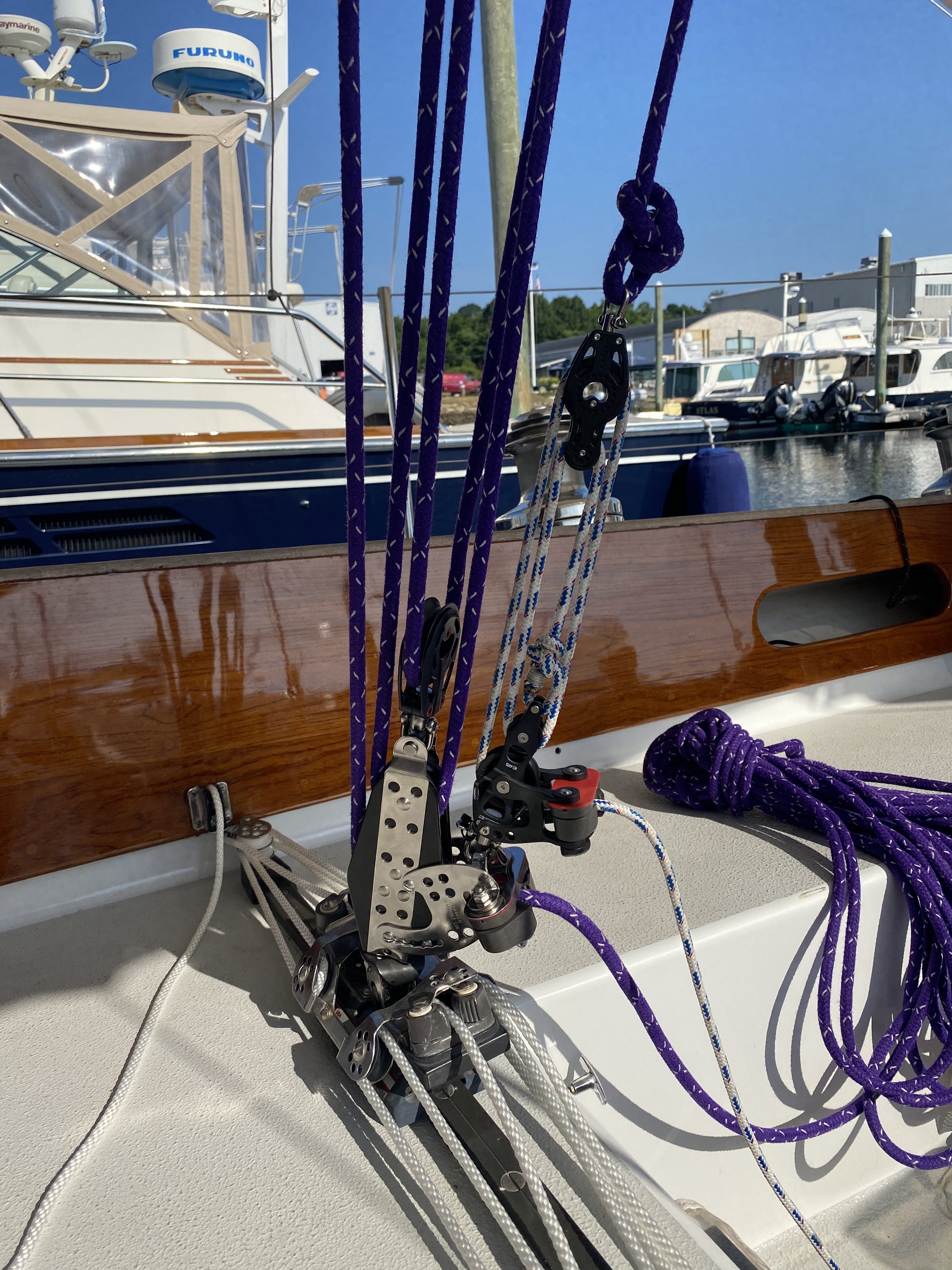
standing rigging, staysail stay, running backs, doublehead rig, heavy weather jib, mast pumping
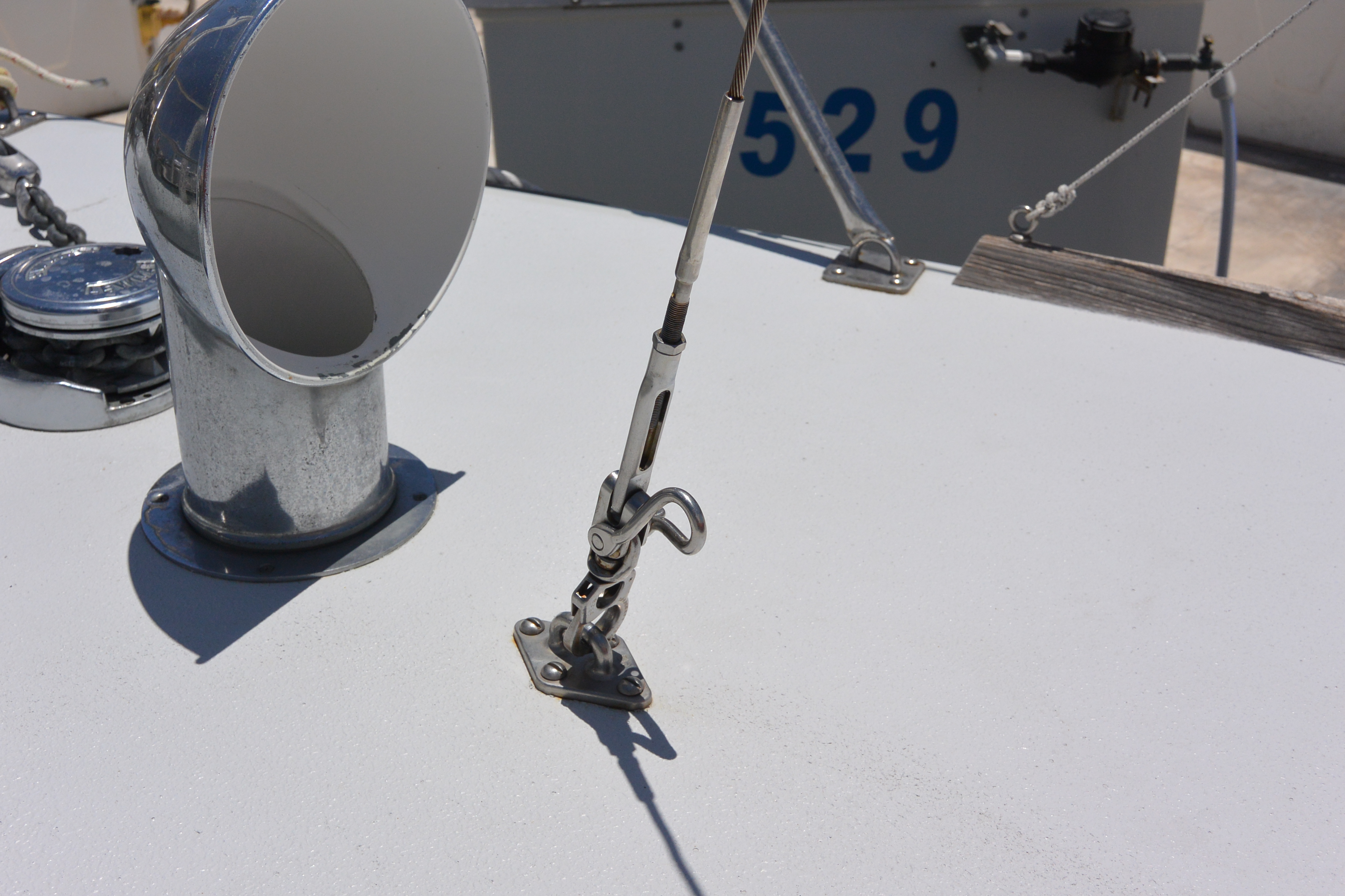
Illusion has a removable staysail stay. The staysail tack fitting is one third of the way aft from the stem to the mast and the staysail stay, when set, runs parallel to the headstay. That is all pretty conventional.
The staysail tack fitting has identical pad eyes above and below the deck, with a G10 backup under the deck. There is a tie wire with turnbuckle below deck. We tension the stay with a half-Navtec turnbuckle above deck, that is allowed to twist due to the swivel on the Tylaska snapshackle. There is a twist shackle used to attach the tack of the staysail. We used the half-turnbuckle on a snapshackle approach so that the hanks on the genoa staysail can slide over it, nearly all the way down to the deck. On deliveries or when cruising we sometimes keep the staysail hanked on the staysail stay, in a bag, when it isn’t being used so it is very nice that the staysail can slide down close to the deck.
We have a 1/4 inch SS staysail stay for deliveries but for Hawaii races when we want to use the staysail as part of a double-head rig with a JT or blast-reacher for the first 2 days, we use a Vectran staysail stay. It gets a little chafe from the hanks on the staysail.
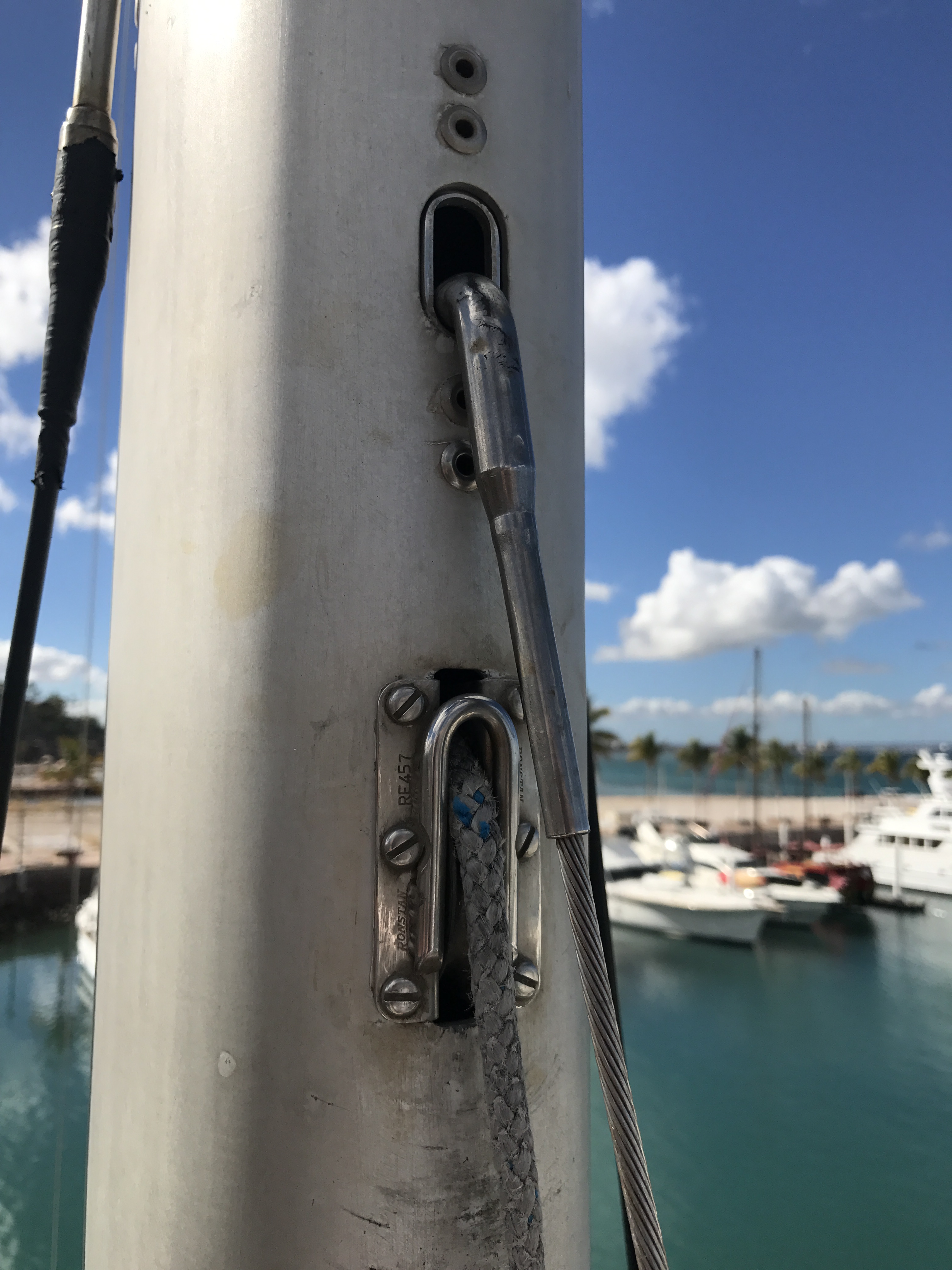
sheave used for both pole topping lift, and as staysail halyard. Note anti-chafe rods.
Our genoa staysail is made very heavy and serves both as a genoa staysail for doublehead reaching on the first 2-3 days of the Hawaii races, but also serves as our heavy weather jib for beating in over 30 knots. It’s size allows it to count as the heavy weather jib under the OSR’s.
We carry the genoa staysail along with a double or triple reefed main in above 30 knots upwind. We’ve carried it upwind in 42 knots true on the way from Hawaii to the Northwest, with a triple reefed main. That was the top end of that combination.
Our removable running backstays attach via T-tangs in the vicinity of the removable staysail stay, which is also attached with a T-tang. For inshore racing we remove the runners and the staysail stay.
Just below the staysail stay T tang is our topping lift exit.

inshore racing mode with no runners and subforestay
We have a somewhat heavier than usual topping lift and sheave, that we use as the staysail halyard as well as for a topping lift. Once the kite is up we disconnect the staysail stay and lash it aft. Of course it has to be stowed aft for dip pole gybes.
Beating, in 30-40+ knots, a Cal 40 balances perfectly under a staysail and reefed main, better than if one uses a storm jib or heavy weather jib set on the forestay.
We have kept the normal Cal 40 forward lowers. They reduce the mast pumping when sailing upwind in heavy air, but for long beats like Hawaii to Alaska or Hawaii to California, it is nice to set the staysail
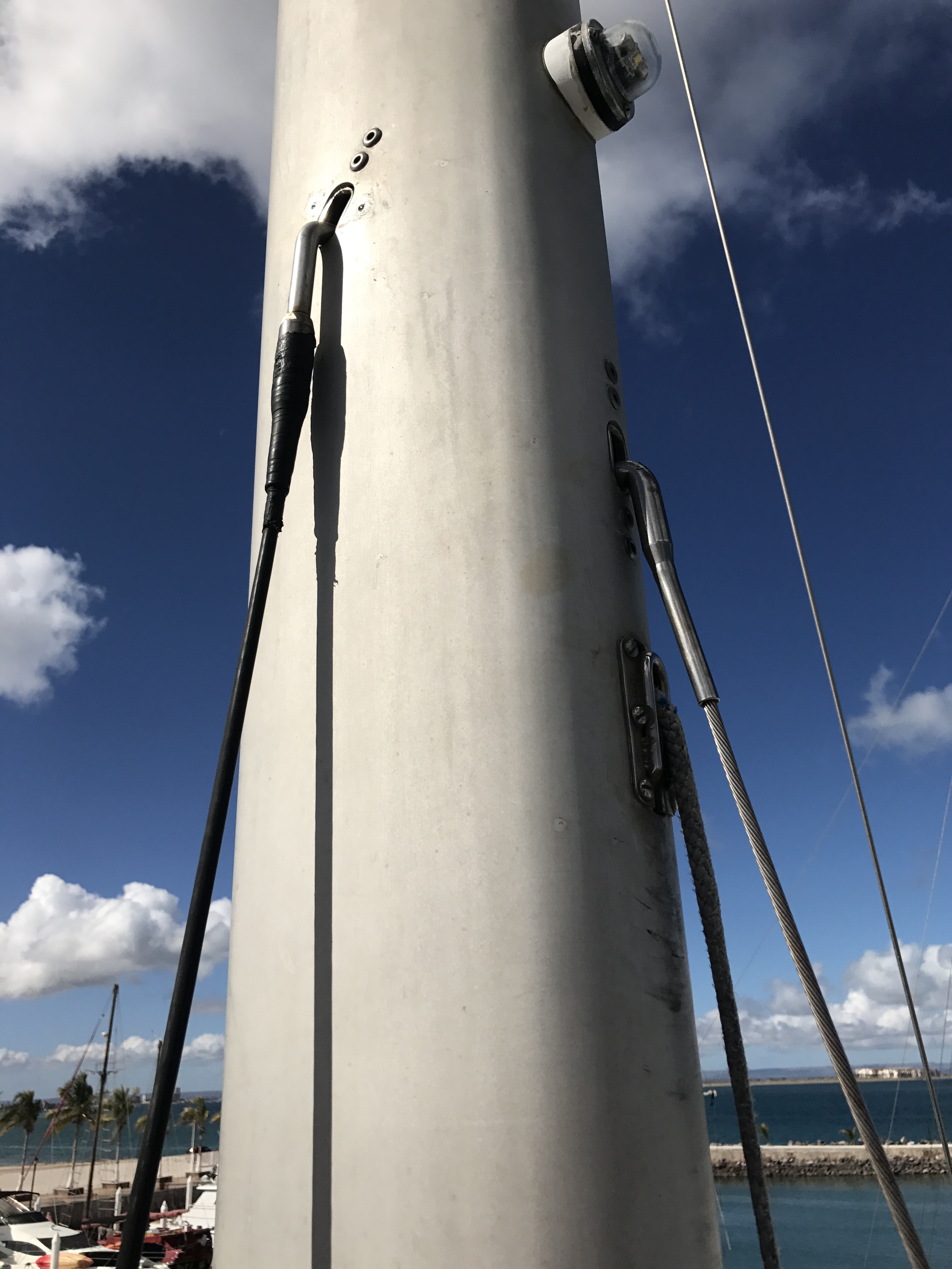
runners and subforestay installed
stay and running backs. With that gear set the mast does not pump at all.
We have Navtec -10 rod everywhere except the backstay is -8 rod. We’ve chosen to keep the forward lowers but if we sailed without them we’d go up a size on the rods, to -12, on the lowers.
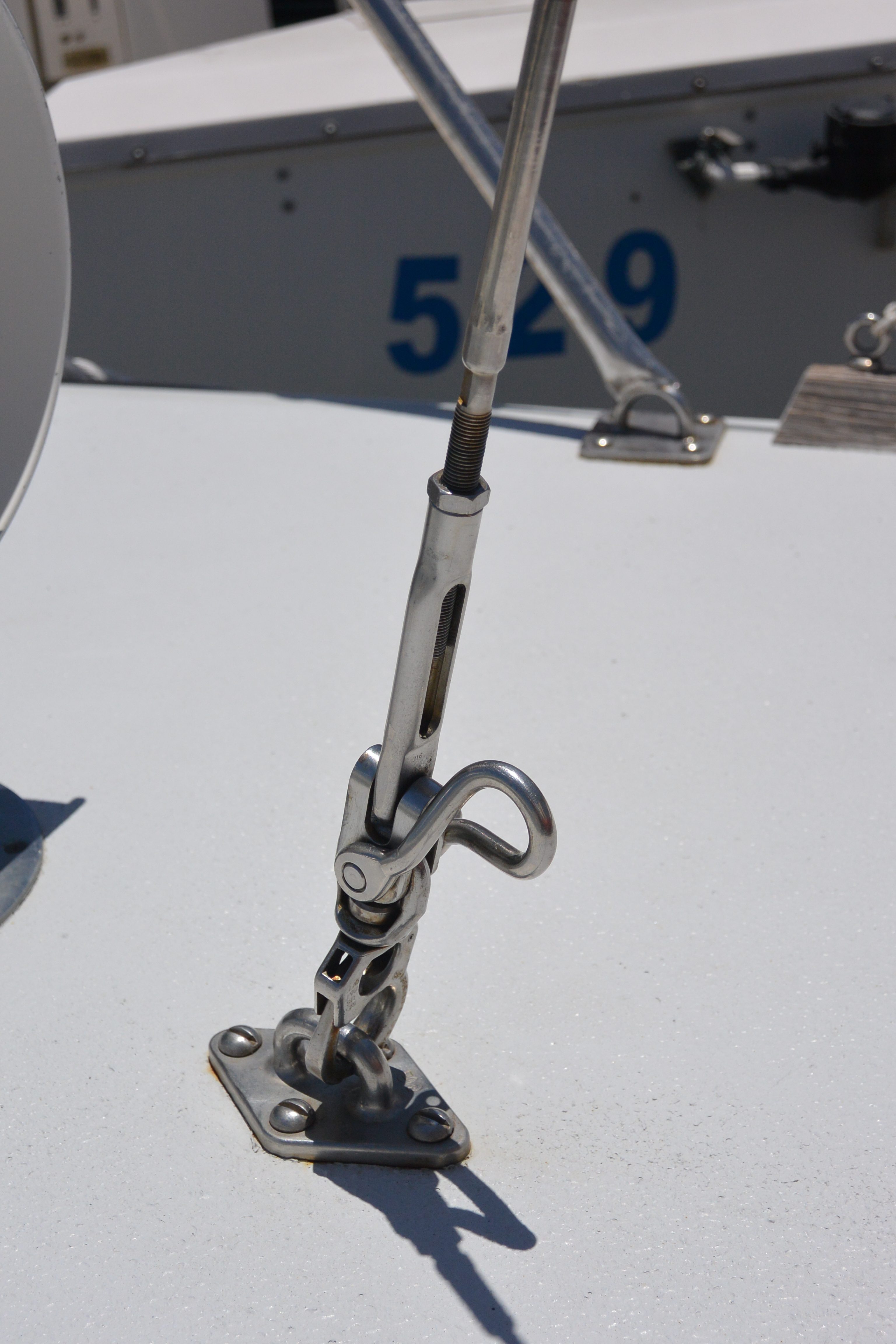
half turnbuckle allows adjustment and allows staysail to drop to deck

tie wire under deck to bottom of chain locker bulkhead
stanchion bases, toe rails, mooring cleats
We located our stanchions to be at convenient locations relative to the sheeting positions, shrouds, and winches, and still meet the maximum OSR spacing. Our hull to deck joint is glassed so we do not need a continuous toe rail to conceal the deck overlap on the hull flange.
So we put on a J24 style toe rail where the stanchion bases are maximum outboard, and the toe rail has independent pieces of teak that are between the stanchion bases. There are several advantages. One is that if you have a collision and damage a piece of the toe rail, it is easily replaced without a major woodworking project. When we milled the original toe rail teak pieces, we made a few spares. Another advantage is the leeward deck drains quickly because there are large open outlets adjacent to all stanchion bases. Finally by having the stanchions maximum outboard, it makes it easier to sheet the foot of the genoa inside the lifelines and outside the upper shrouds, and gives more clearance to winch handles.
For backup plates we use 1/2 inch G10. We filled the gap outboard of the deck core and inboard of the hull flange with epoxy mixed with filler.
The mooring cleats are maximum outboard right on the toe rail so we don’t need chocks, and there is no chafe. The mooring cleats are similarly backed up with G10.
The bow and stern pulpit legs terminate on pad eyes. We find we use the additional attachments often when changing headsails etc.
We were a bit worried that the lack of a continuous toe rail might change the Cal 40 look, but it looks fine.


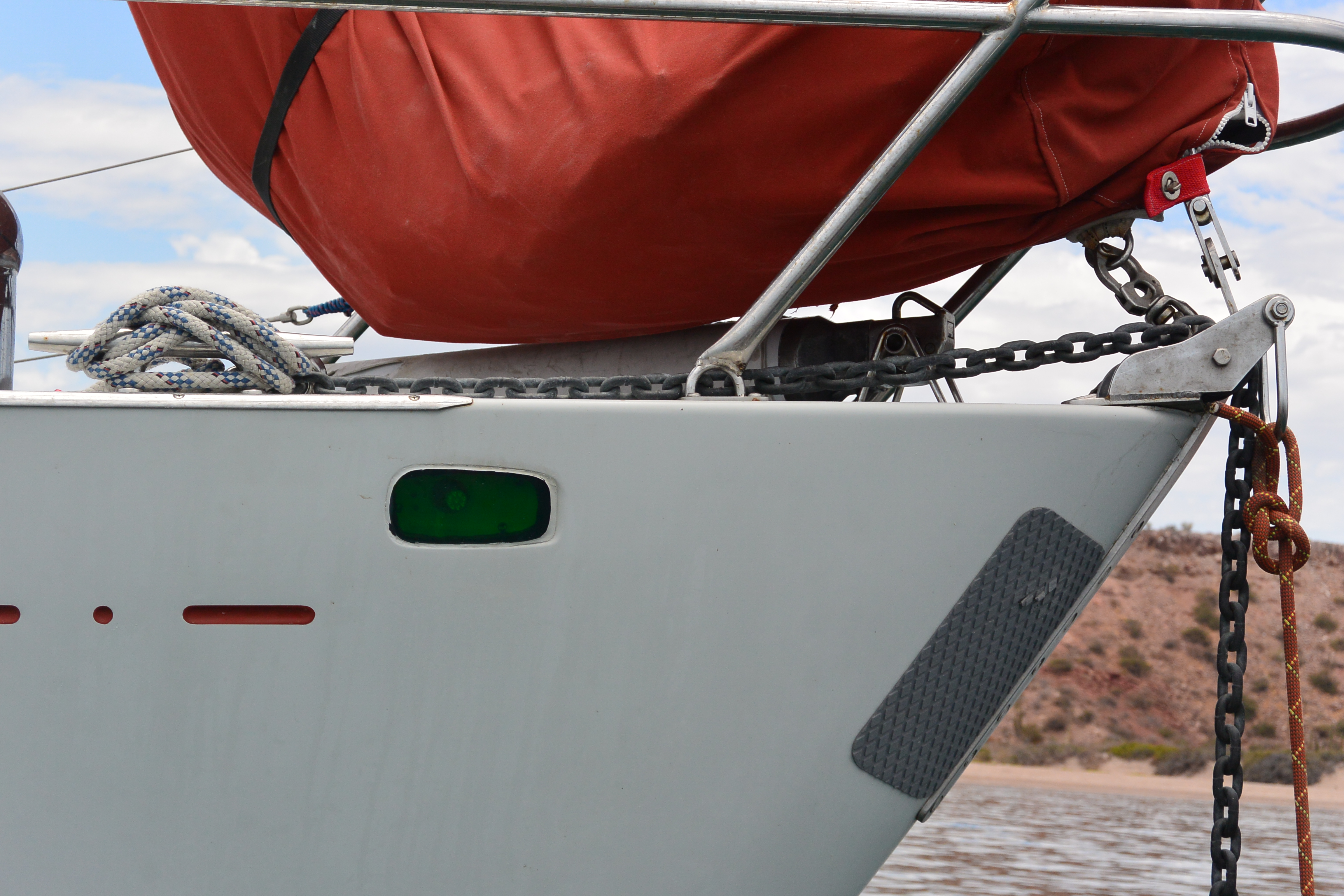


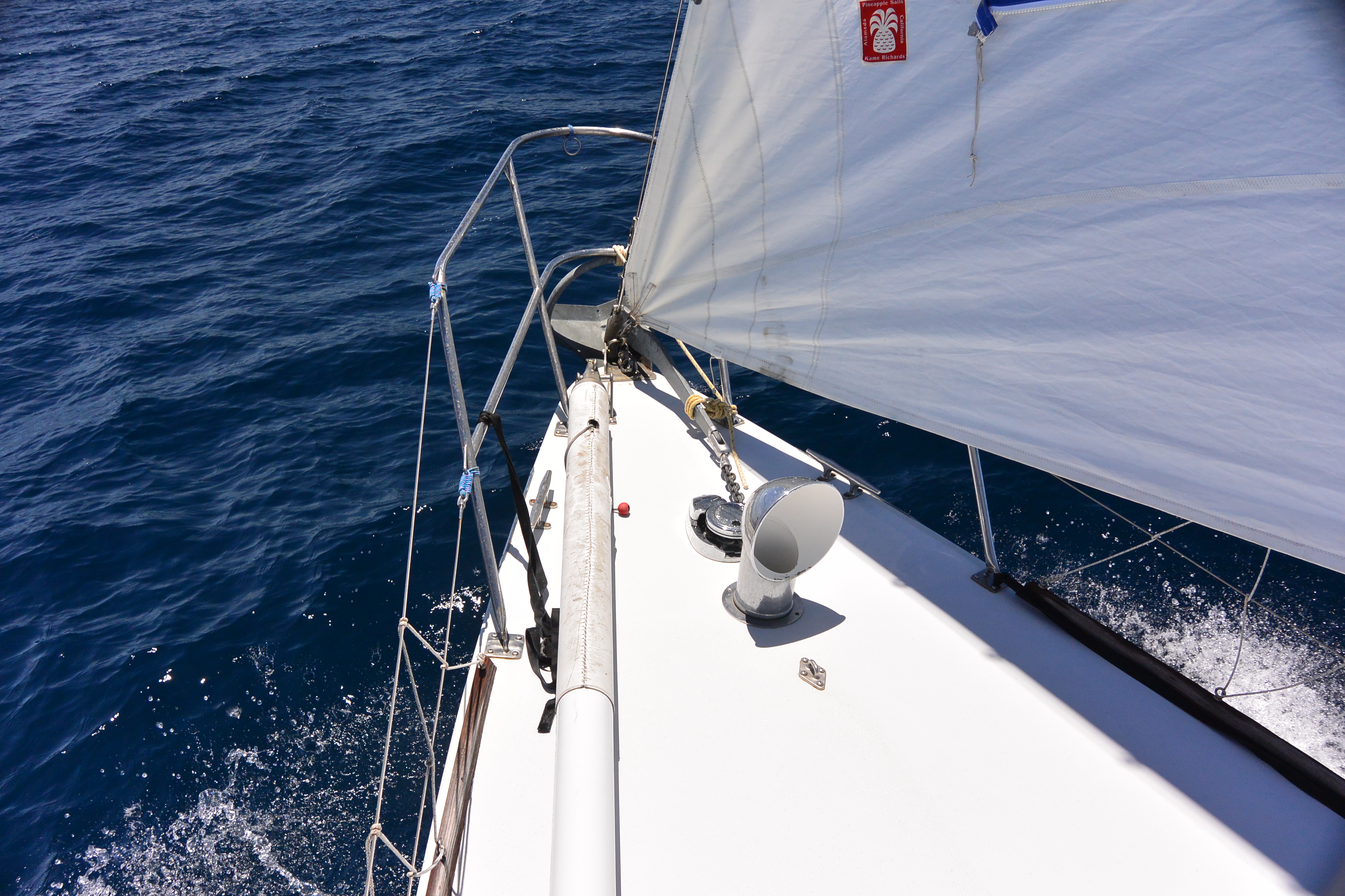
anchoring gear, chain storage, bow roller
When cruising Illusion we temporarily install an anchor windlass. When racing, the windlass comes off and we have a painted and nicely beveled G10 plate that attaches to the deck with the same fastener holes and is painted to match the deck.
We initially installed a Lewmar Ocean 1 windlass, in 1996. We chose the gypsy-only unit to reduce the size of he windlass on deck. As we accumulated experience cruising, we discovered that it was a mistake to have the gypsy only unit and we bought the parts to modify the Ocean 1 windlass to be a gypsy-capstan unit. There have been several times when it would have been enormously useful to have had a powered winch on the foredeck to use with a kedge or second anchor. Additionally, it is easy to lead a halyard to the windlass drum making it easy for Sally to hoist Stan up the rig. Prior to adding the capstan Stan climbed using jumars. The extra size of the addition al capstan drum on the foredeck isn’t a problem when cruising and of course when racing, the entire windlass is off the boat.
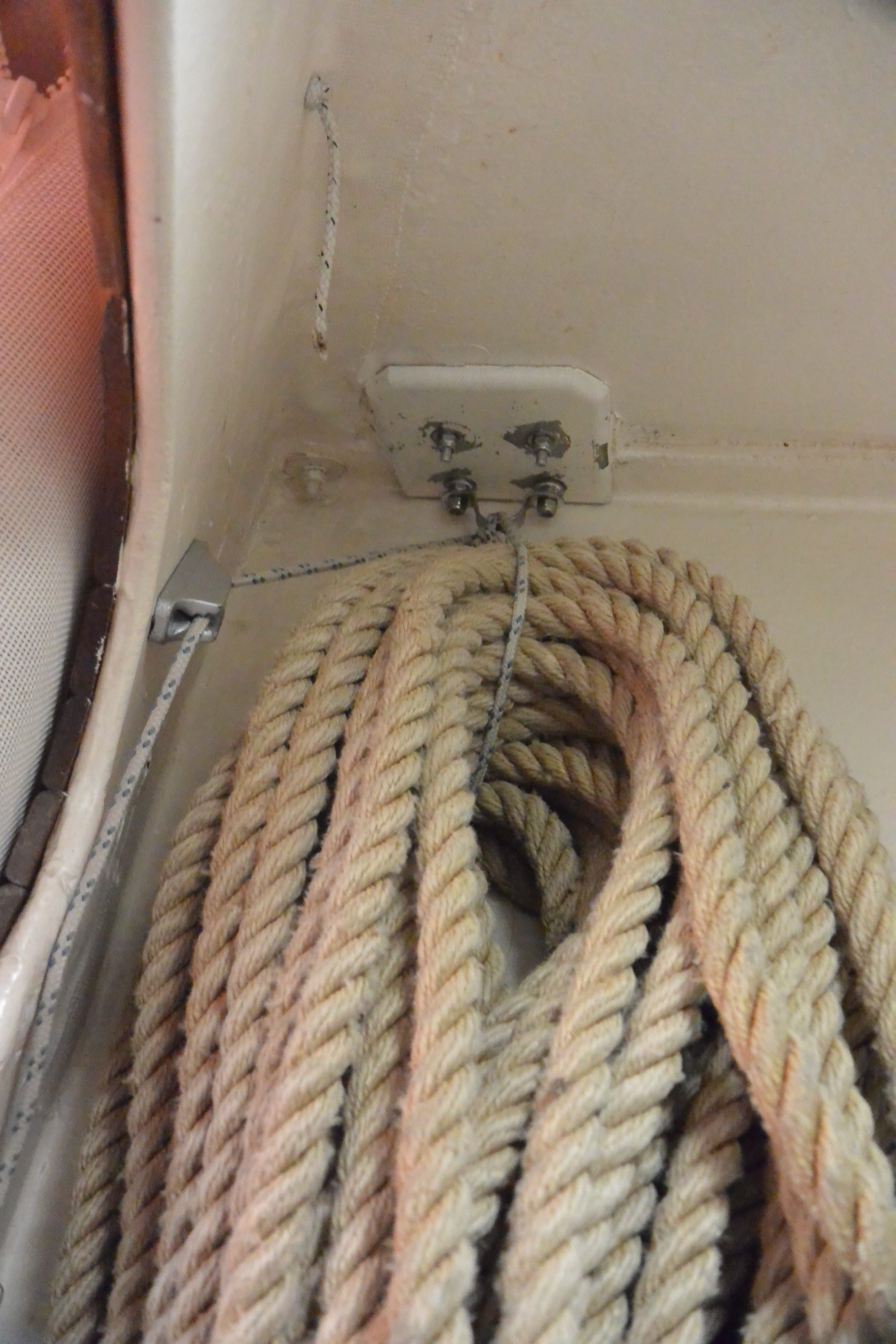
When cruising we carry 200 feet of 5/16 G4 chain, 250 feet of 3/4 nylon rode, and a 44 lb Rocna anchor as our primary ground tackle. We have only used the nylon rode once, when we had to anchor in a depth of 100 feet in Alaska. We carry a Danforth HT20 for a stern anchor and a Fortress FX37 as a storm anchor with associated rodes.
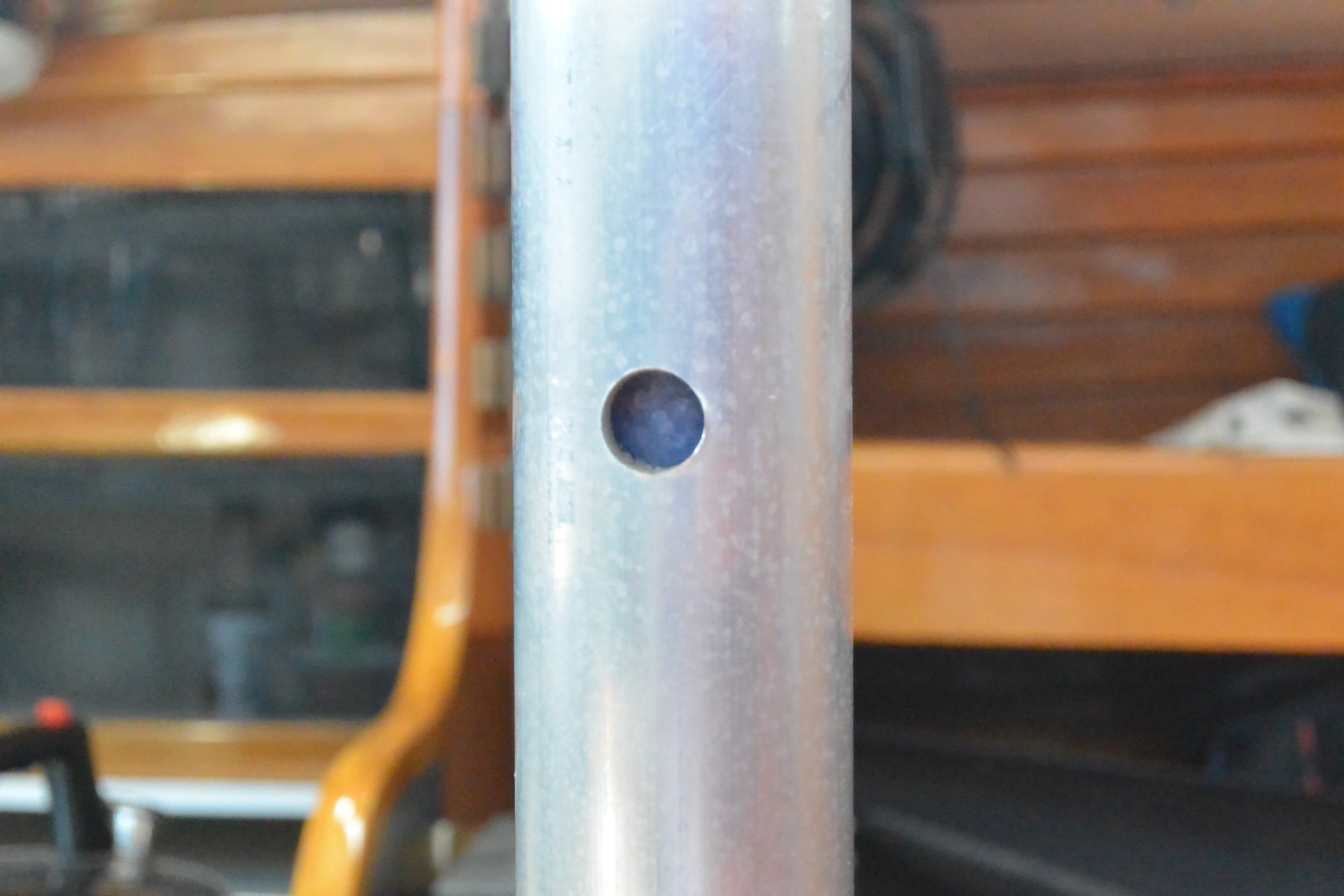
We had the normal headaches with the chain “castling”, i.e. piling up into a cone, then toppling over, which makes a major hassle to pull the chain out the next time you drop anchor. The frustrating solution, especially when doublehanded which is nearly all we do, is for one person to be in the forepeak spreading the chain around.
We stumbled on a terrific solution for Cal 40’s. The Cal 40 has a web that attaches the two sides of the hull in the forepeak locker. Forward and below the web is a space between the web and the hull, that extends down under the storage area under the forepeak bunk, and opens to the bilge just forward of the mast step. As you can see in the photos, we cut a round 6 inch hole in the web, positioned just where the chain falls. The chain neatly falls through that hole and then slides aft and down. All 200 feet of 5/16 chain fit between the web and the hull, and the weight ends up much farther down and aft than if the chain just sits in the chainlocker. It works so well we wonder whether Lapworth had that in mind originally. It is the best solution to chain castling that we’ve seen on any boat.
We tie the nylon rode up under the gunnel to keep it dry and out of the way. We can quickly release the coil of nylon if we need it by undoing the clam cleat.
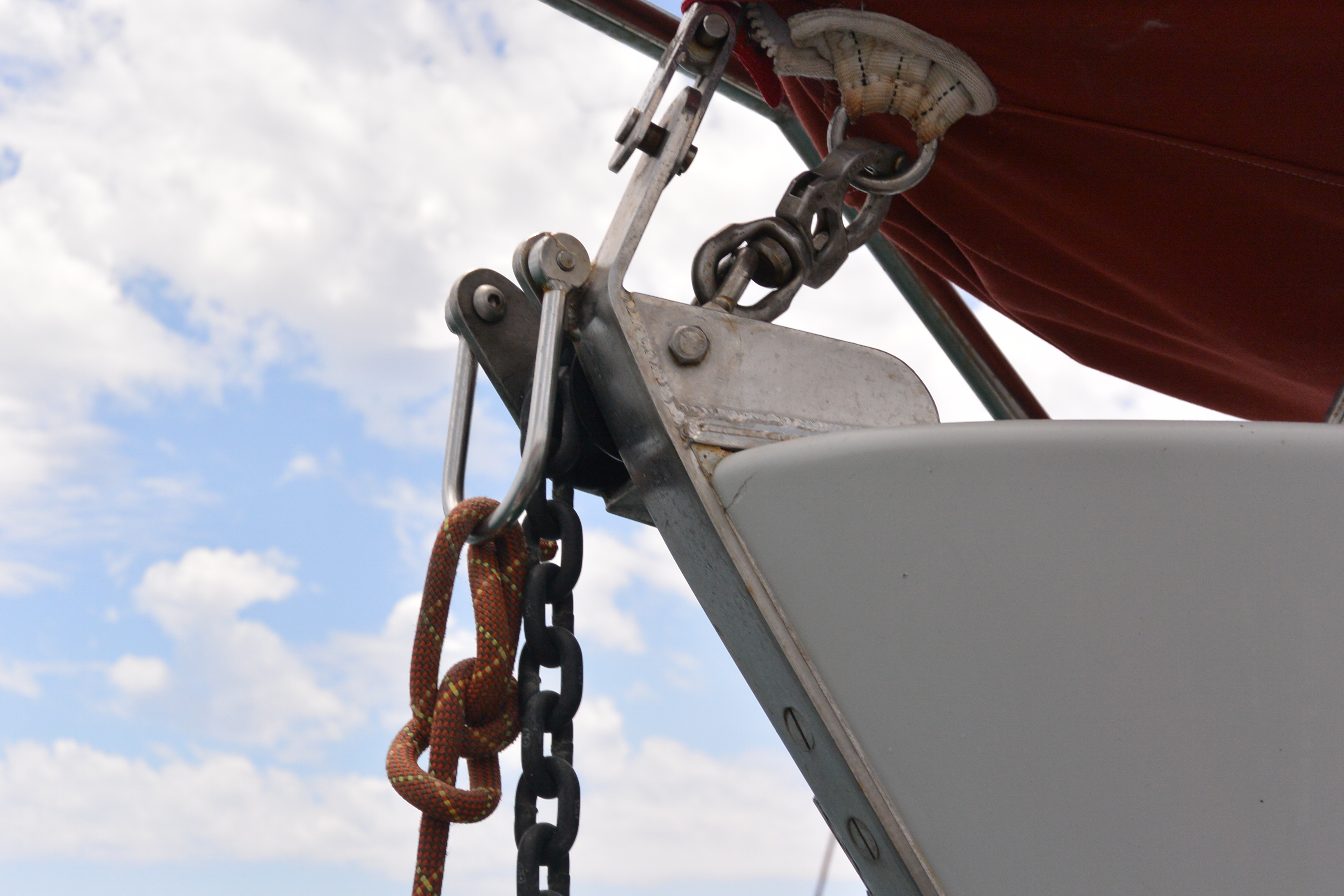
We replaced our bronze stemhead fitting with a fabricated SS one. The forestay chainplate is in exactly the same location as using the class stemhead fitting, so we are still a Cal 40. The stemhead fitting includes a roller that is right adjacent to the chainplate. It is enormously strong including for sideways loads, and adds nearly no weight because it is part of the stemhead fitting. Having the chain roller be strong for side loads turns out to be important given the tendency for Cal 40’s to sail around at anchor.
We don’t miss the sharp mooring line chocks that were part of the original stemhead fitting. Instead we mount our mooring line cleats right on the rail so that mooring lines tie to them and have a fair lead without chocks and with no chafe. I recall that George Griffith expressed frustration that the Cal 40 was not set up this way originally.
We have a large shackle that keeps the anchor in the roller when under way, keeps the chain from jumping the roller, and that we also use to dead end the inboard end of our snubber when we are at anchor. By dead-ending the inboard end of the snubber to that shackle, there is never any chafe on the snubber or on the hull as the boat sails around at anchor.

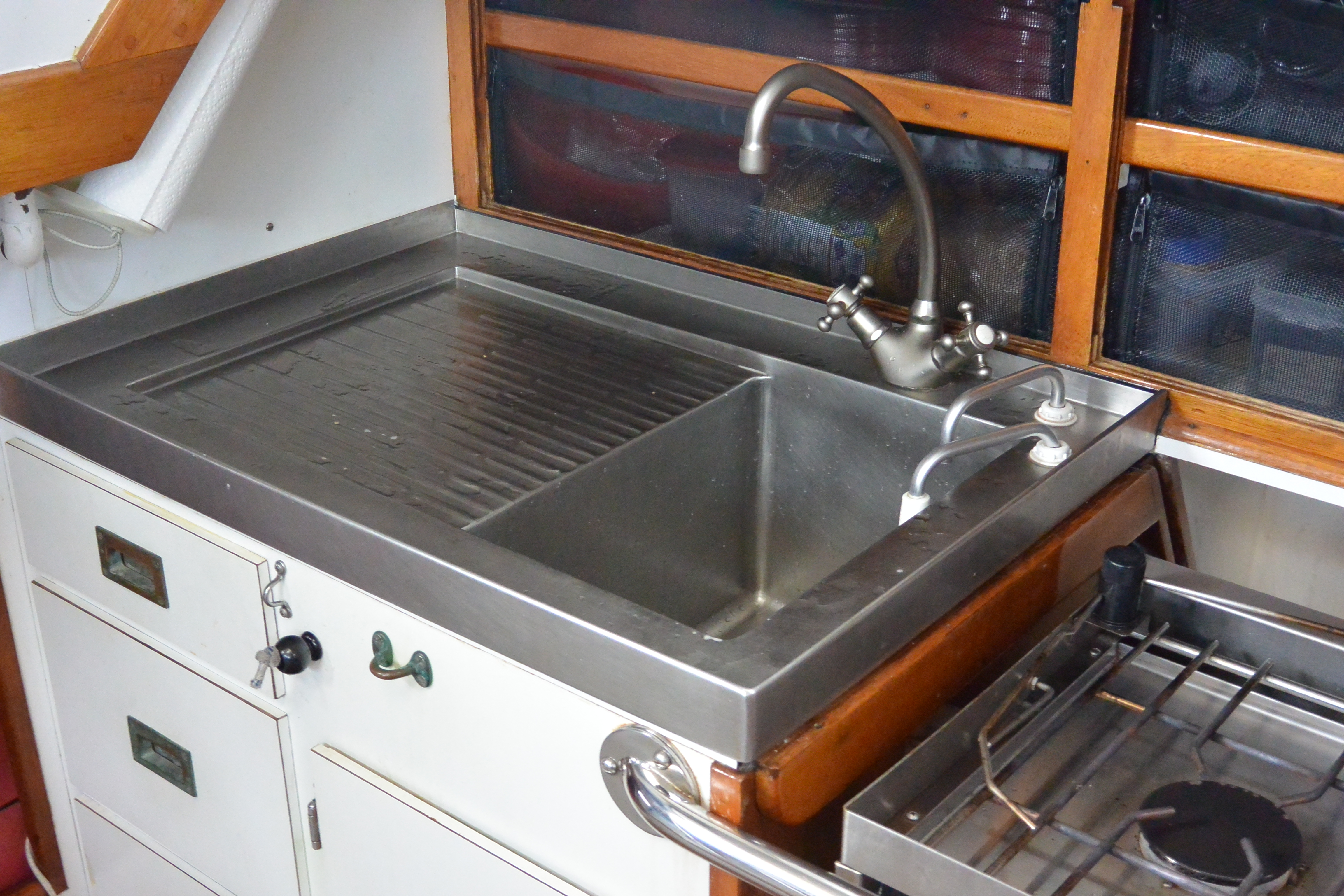
emptying sink when under sail, new counter
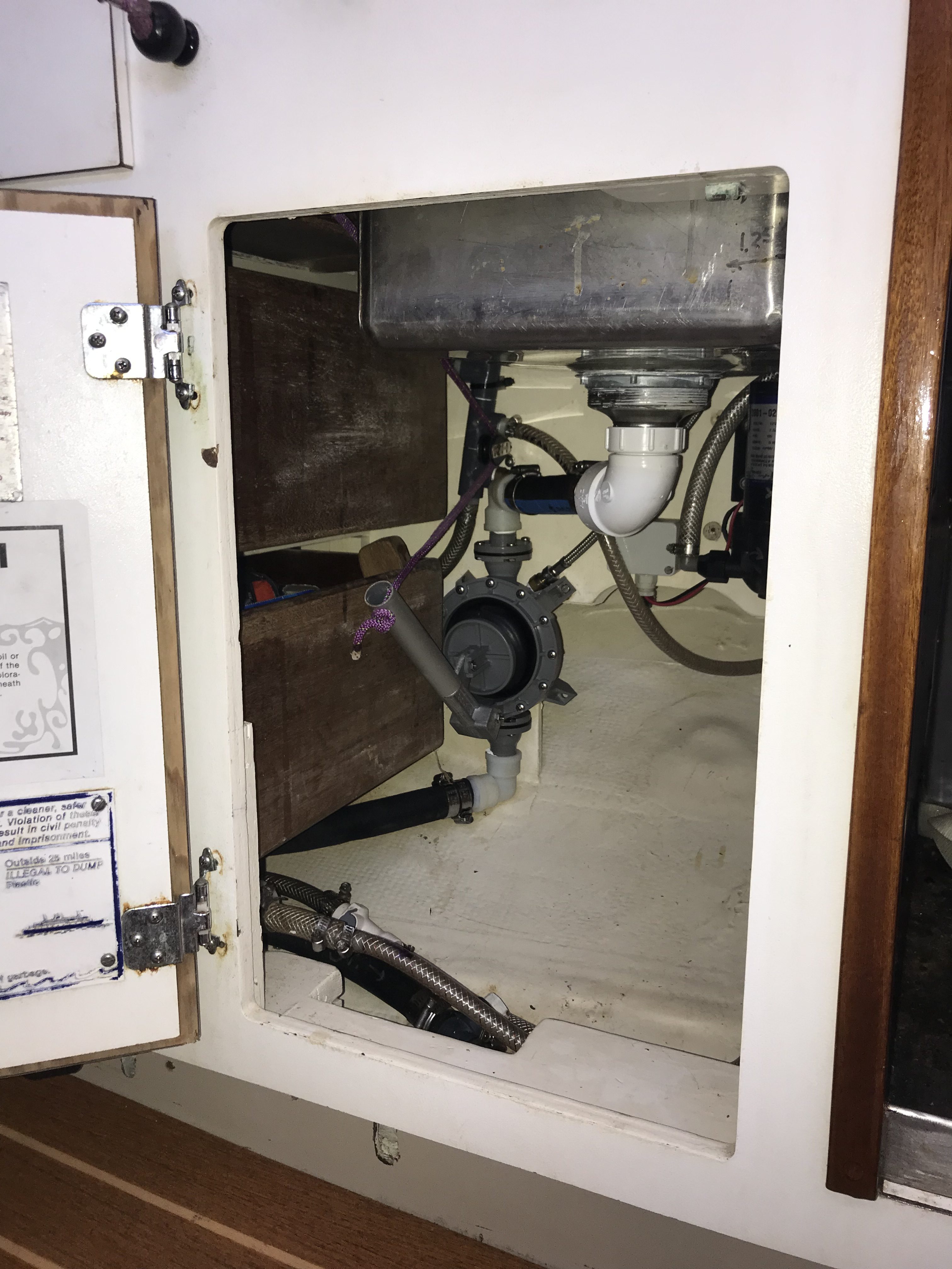
sink drain plumbing and pump
Cal 40 galley sinks are located on the port side, so they fill with water when sailing hard on starboard tack. To make the sink usable on starboard, particularly on the Transpac when you reach for a few days, we borrowed an idea from kayaks and Optis. We put a Bosworth Guzzler diaphragm pump under the sink, and made it operable by pulling on a line. The Bosworth pump company makes pumps that are perfect for this and have a spring internal to the pump so that the handle extends by itself and only needs to be pulled down. It works great. In a few pumps you can empty the sink even when rail down on starboard tack. This is one of our best upgrades. The line with the black ball, coming out of the cabinet below the sink, is the line that actuates the pump and empties the sink. There is a Harken Bullet block turning the line under the pump handle, and a Harken upright Bullet block just inside the fairlead in the cabinet through which the line runs. An additional benefit is that any diaphragm pump has two integrated valves, so if you forget to close the thru hull when beating on starboard, the sink doesn’t fill, although we also have a normal valve that we shut off when we remember.
As is visible, we removed the dedicated sink drain thru hull and instead have plumbed the sink drain into the port side cockpit scupper. It tees into the scupper above the scupper thru hull, and has its own ball valve which we shut off when the boat is unattended. The objective was just to minimize thru hulls.
Sally found an outfit that makes custom SS sinks and counters for restaurants and fishing boats, and had them make a custom sink with built in drainboard and fiddles for Illusion. It allows Stan to spash water around with abandon when washing dishes and it all finds its way down the drain.
In the photo above you can see two quick disconnect plumbing fittings. We have two freshwater tanks (one in bilge and one under head counter) and two freshwater pumps (an electric pump and a foot pump in the galley). These quick disconnects allow us to hook either FW tank to either pump. If we are really trying to conserve water we run the pressure pump on saltwater, leaving the galley foot pump as the only source of freshwater on the boat.

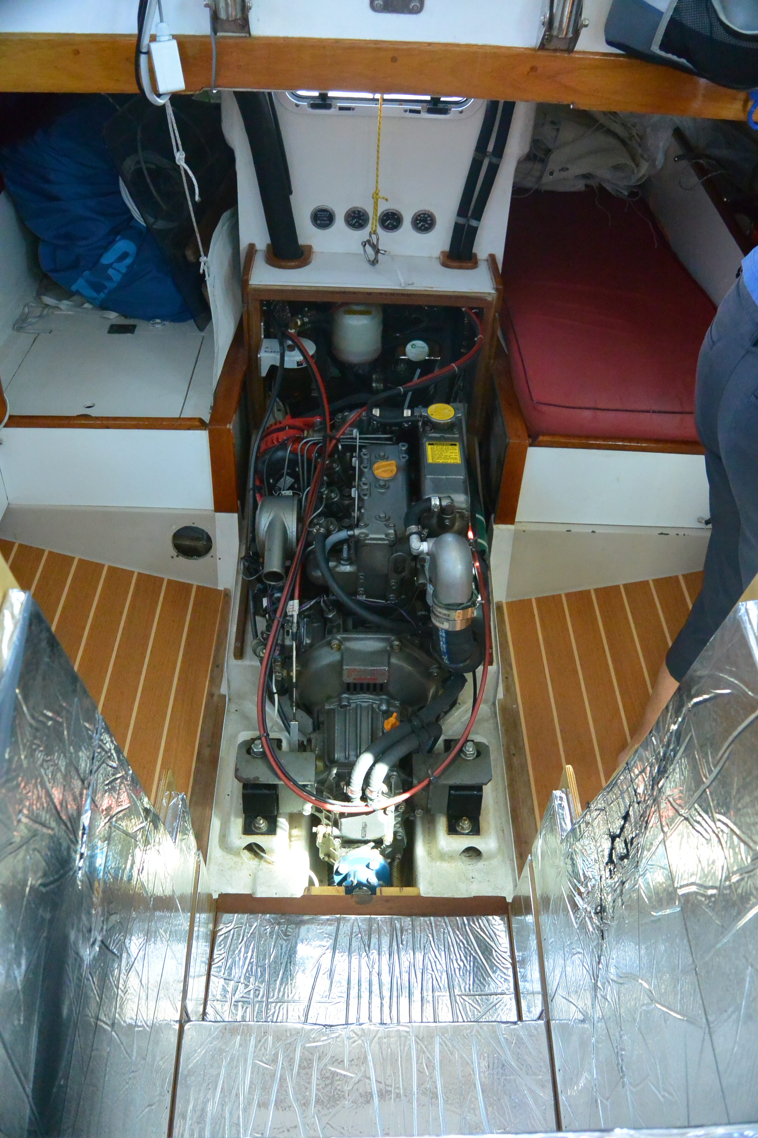
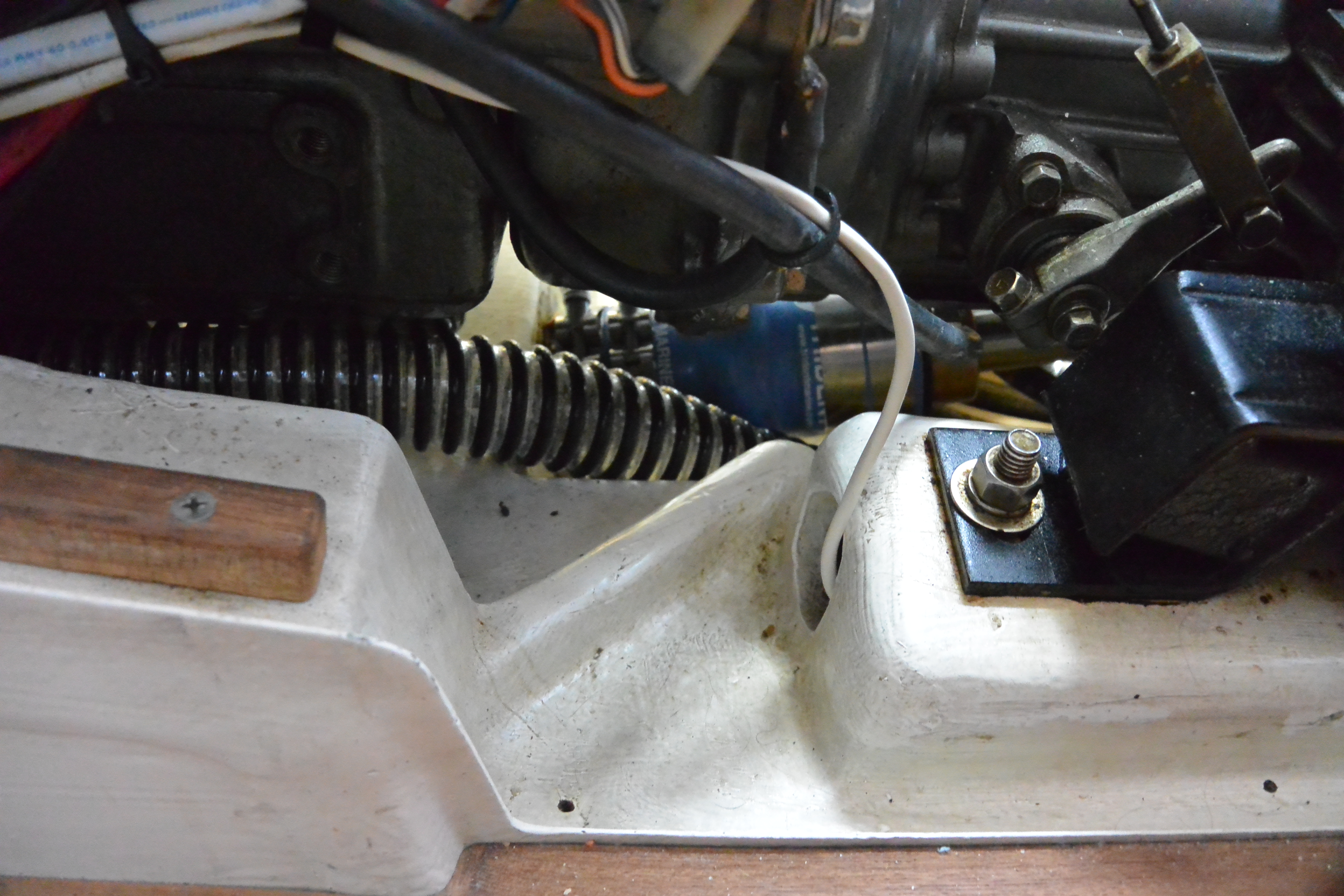
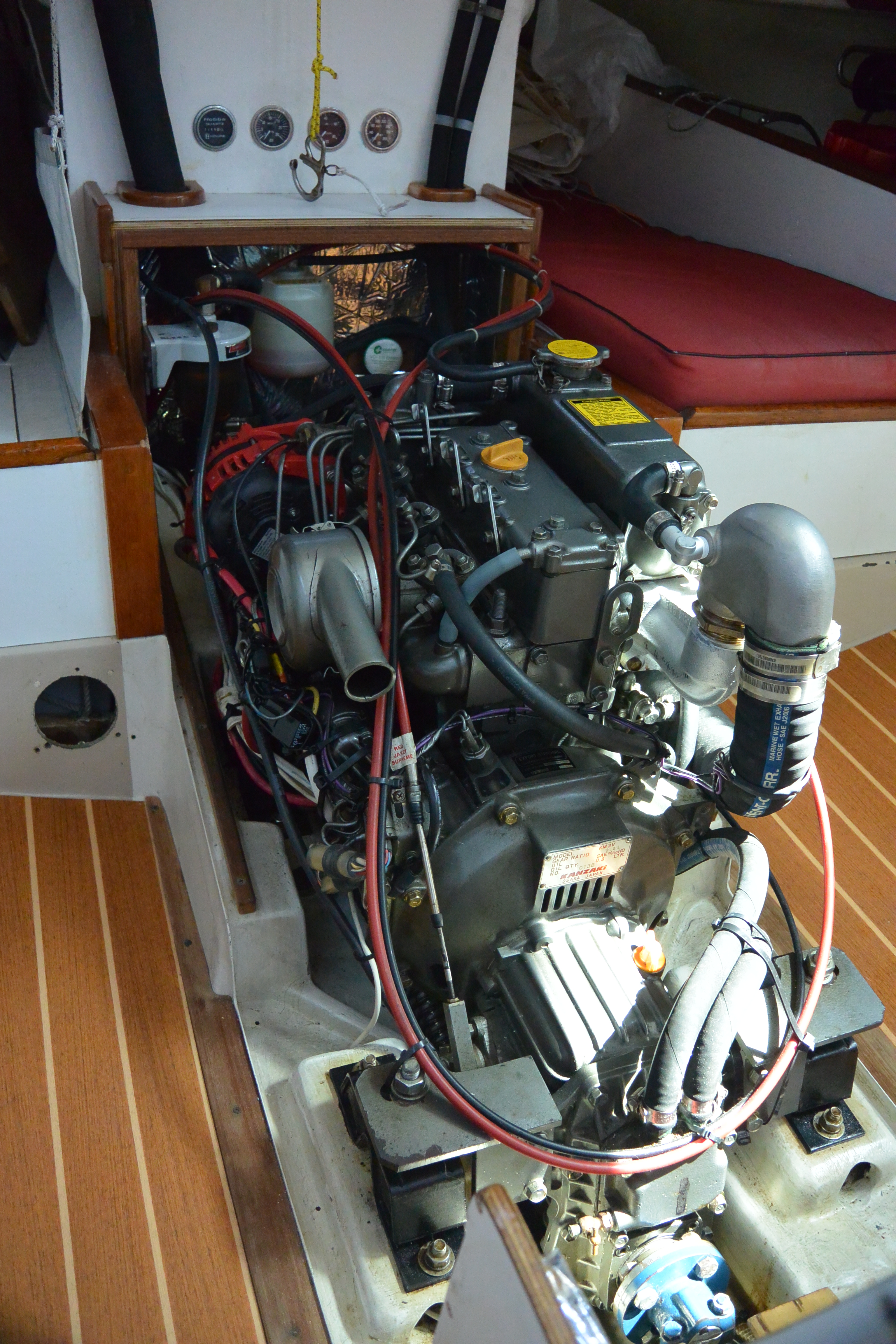
Engine installation and engine box.
We installed a Yanmar 3GM30FV. Bob Pearce did the installation, and did an outstanding job. We use the 2.61 reduction gear, the built in V-drive, and an 18 inch two-blade “classic” max prop with the pointy tip at the hub. Cal40’s originally came with 1 1/4 inch shafts that were machined to 1 inch at the prop to allow a smaller hub. Our shaft is 1 1/4 the entire way so we have the larger max prop hub. That makes the bearings in the hub larger so that they are very long-wearing and we’ve never had the play in the blades increase.
The propeller rpm is about 1000 at our cruising rpm with our transmission, so the propeller tip speed is about 80 ft/sec. 95 is about the top limit for tip speed for a Max Prop because it has no twist in the blades and the tips can cavitate if they run too fast. It is very efficient with the large prop. We’ve tinkered with the pitch and ended up with 20 deg, which is equivalent to about 12.4 inch. That has us powering at about 6.25 knots at 2600 rpm, using about 2/3 gallon per hour. It is slightly “over-propped” at that pitch, so wide open the engine only gets to about 3300 rpm.
We use the stiffer Yanmar 150 mounts, and use a Norscot stuffing box, which we’ve had great luck with. It’s great to never have ANY saltwater or mist under the engine where the stuffing box is on a V-drive.
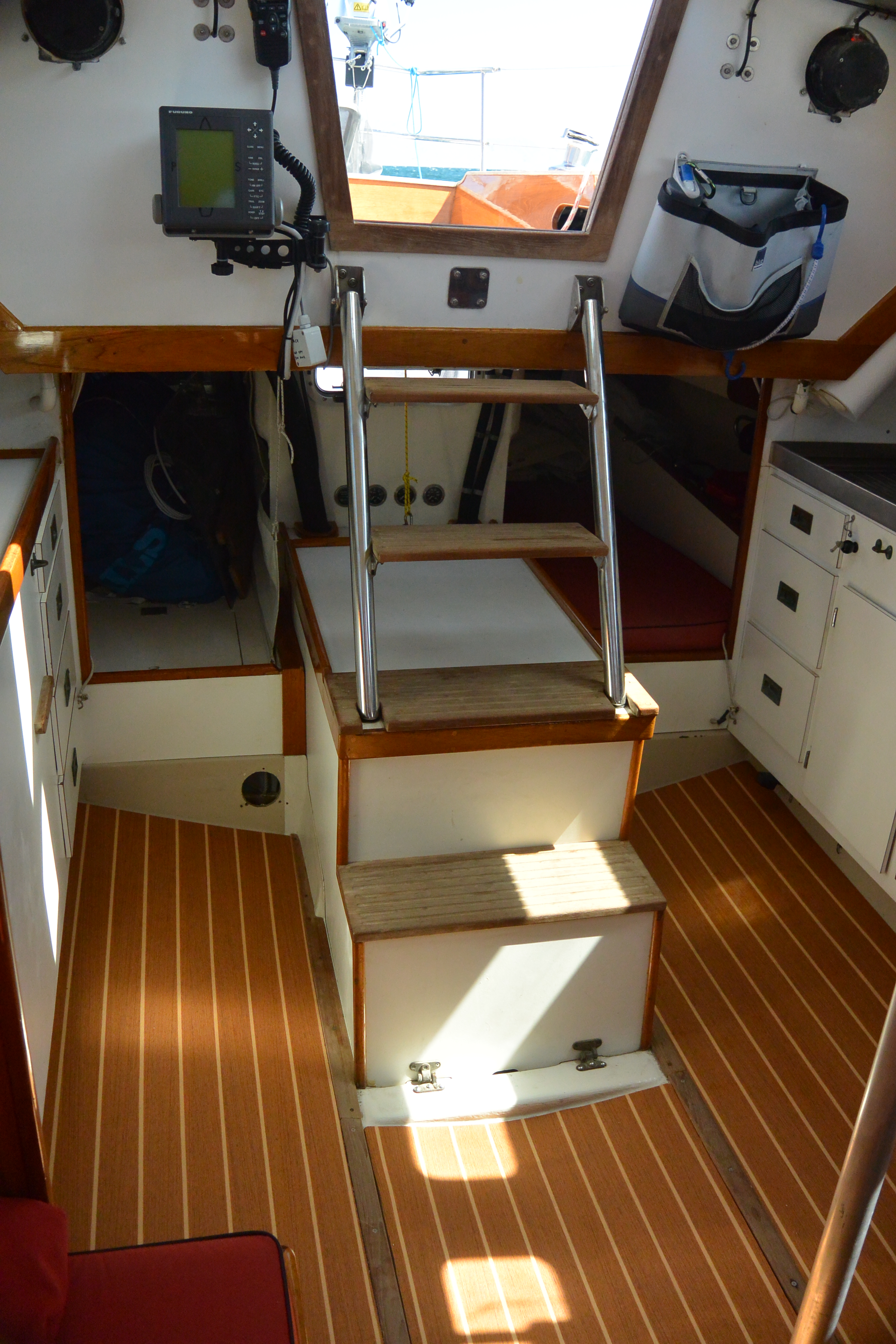
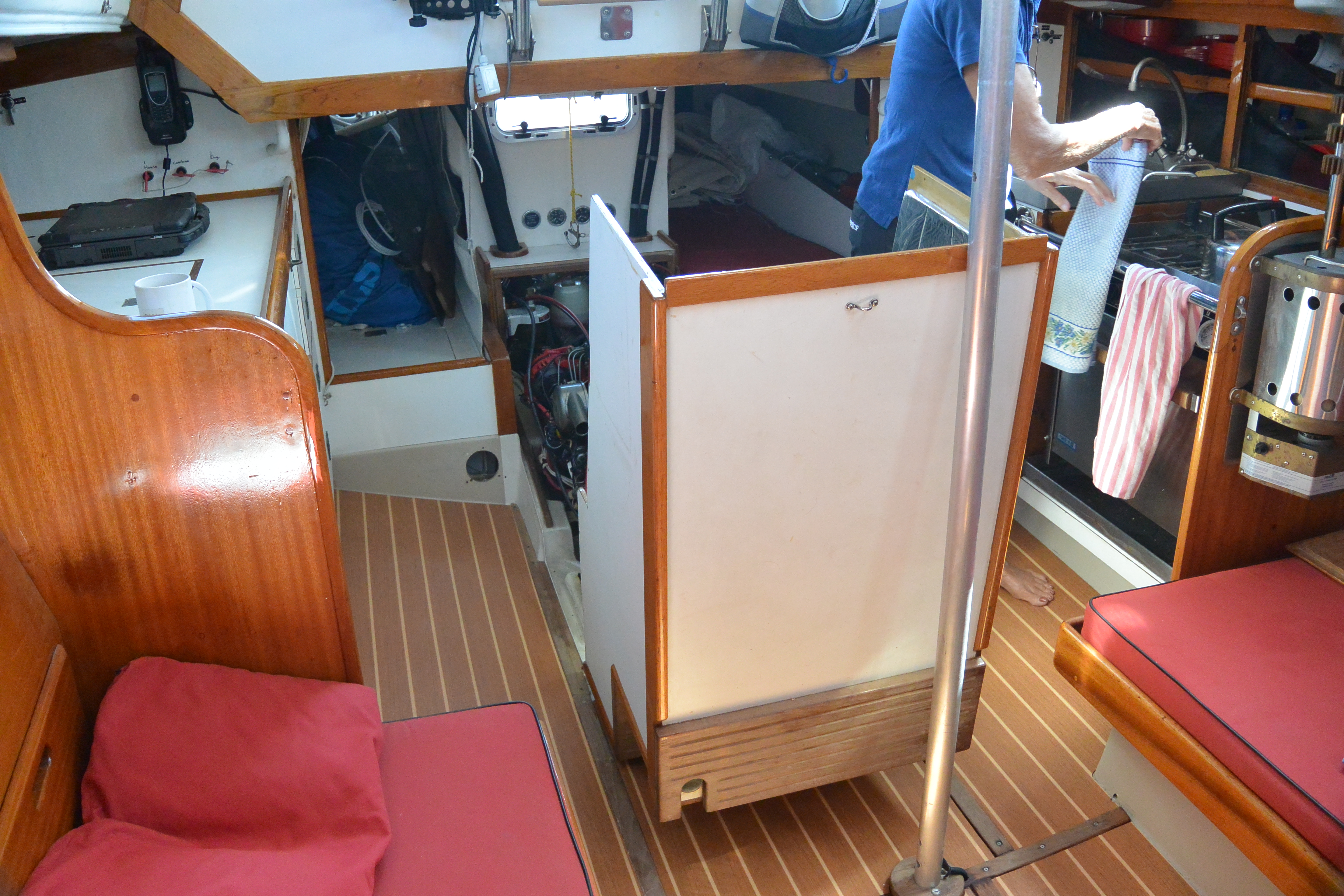
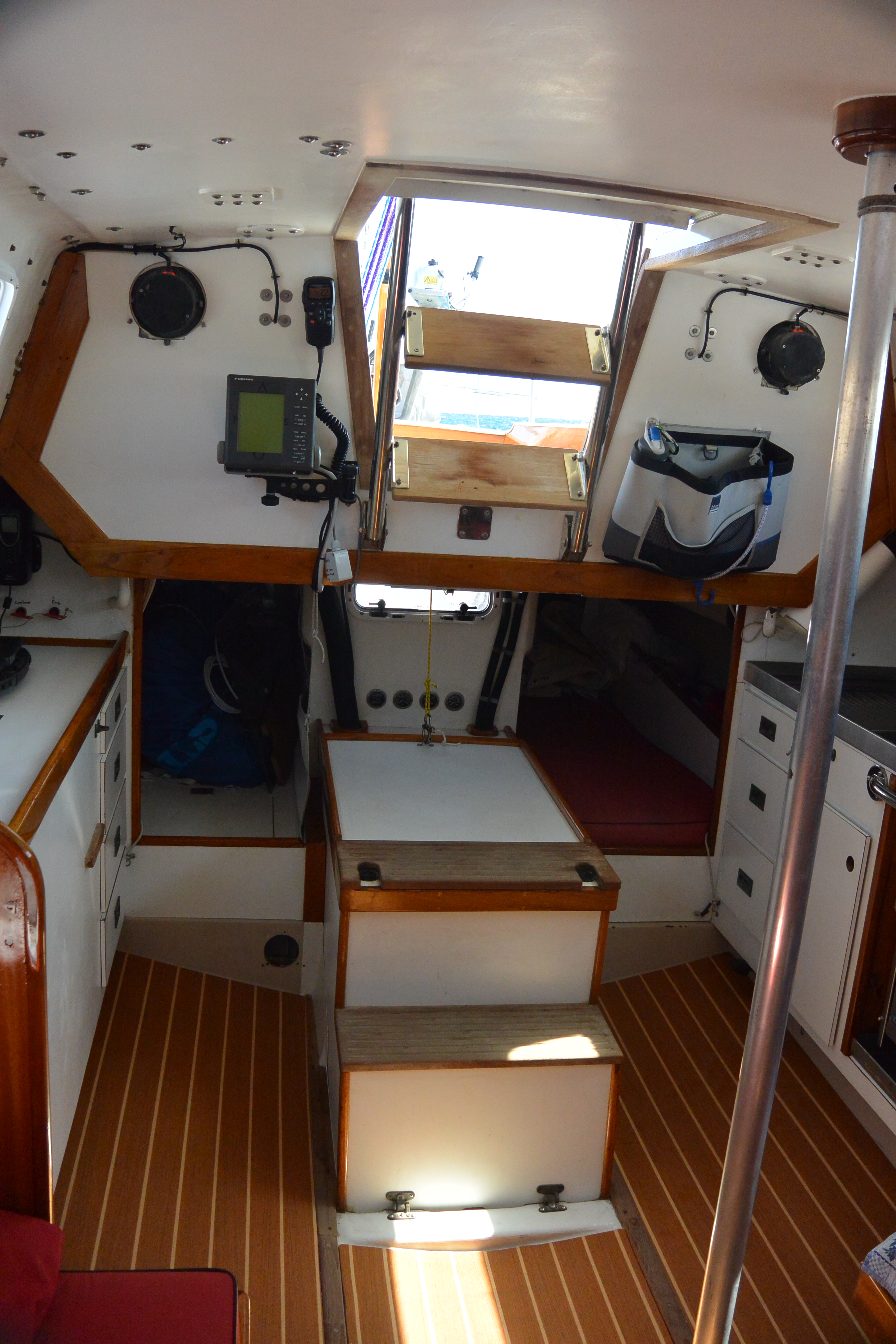
When we bought Illusion, there was no engine and the Walthers V-drive was ruined. We found that if we used an engine with a built-in V-drive, and moved the engine forward and down in the boat, it could perfectly connect to the existing shaft location. Of course we had to build new mounts. Moving the engine forward, down, and saving the weight of the Walthers V-drive were bonuses of this approach. Using an engine with an integrated V-drive also allowed us to move the forward edge of the engine box aft, so we gained room on both ends. Moving the engine forward allowed us to put in a bulkhead at the forward end of the cockpit well, i.e. the aft edge of the bridge deck that runs down to the hull. This bulkhead stiffed the boat and carries our traveler load.
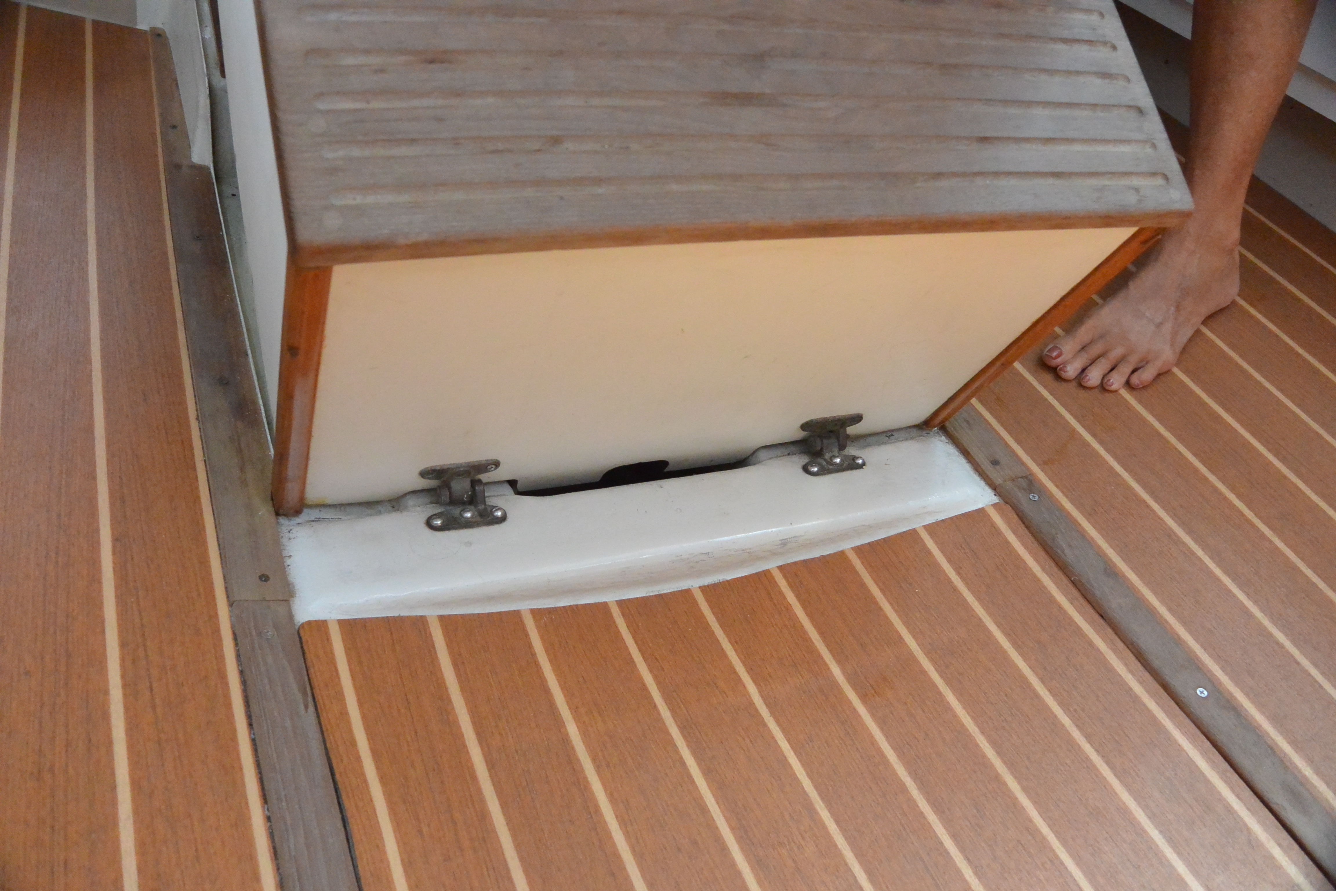
The engine box pivots on two removable spring-pin hinges on its forward lower edge. We designed the engine box so that when it pivots up and forward, it just clears the wood trim under the companionway. The box is all one piece so that water that comes down the companionway never can get to the engine, it just flows around the engine box then onto the cabin floor, then into the keel well. If we need to do serious work on the engine we remove the box by pulling the two hinge pins and set the box on a settee.
The box is shaped to be used as the two bottom steps of the companionway ladder. The first step just clears the transmission/v-drive, the second step clears the top of the exhaust mixing-U, and then we have two more steps that are part of a SS ladder that pivots down from the companionway.
It’s hard to describe but the photos might make it clear.
The gauges above the engine box are engine-hours, oil pressure, coolant temperature, and fuel vacuum. They are all mechanical gauges except of course for the hourmeter.
The waterlift muffler is aft of the engine, against the new bulkhead that is at the forward side of the cockpit well. The exhaust goes up from the waterlift muffler to just under the bridge deck, and then goes aft via a fiberglass exhaust tube, at a slight angle down, all the way to the transom.
We replaced the standard Yanmar-Hitachi alternator with a Balmar, and upgraded to a serpentine belt. It is terrific to never have any belt dust.


Freshwater and diesel tanks in keel well, bilge pumps.
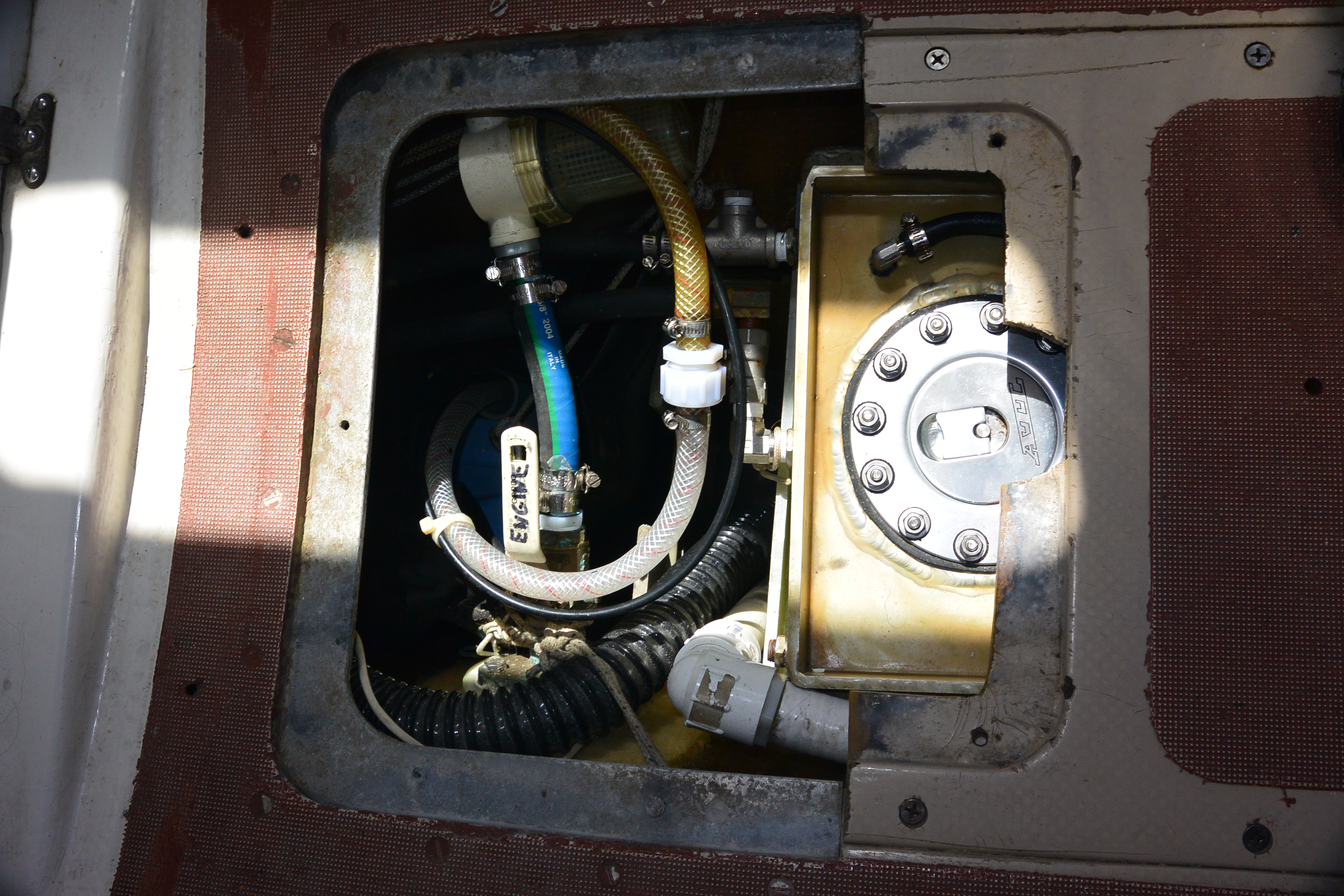
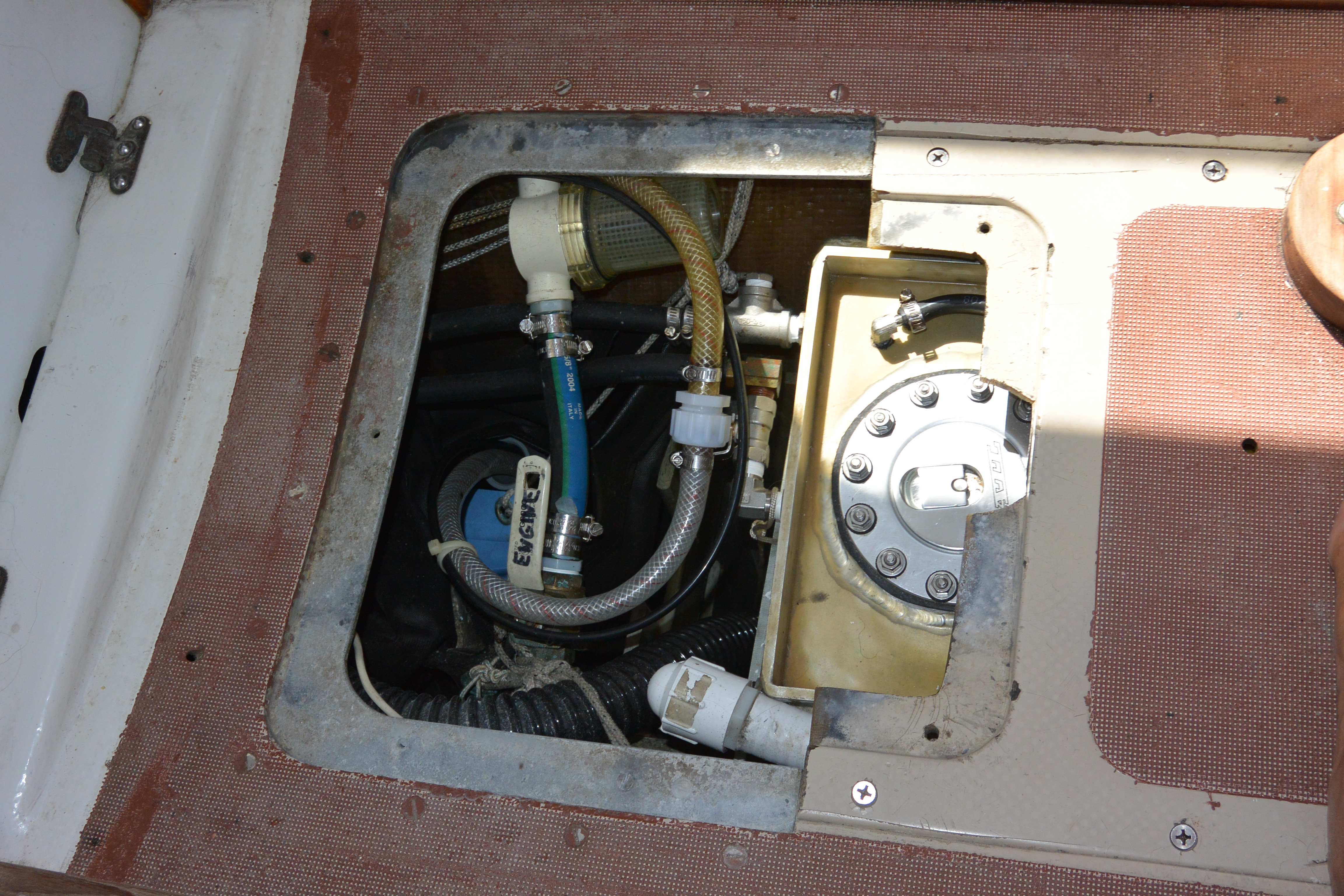
We have both the diesel fuel tank and fresh water tanks in the keel on Illusion.
The diesel tank is clearly visible, and sits on top of the encased lead ballast. It is a conventional aluminum tank that is painted with Gluvit (thus the gold color) and sits on two G10 fore-aft runners so that water can pass underneath it from forward in the boat into the keel well. It is custom made to fill the area above the lead and holds 50 gallons.
We fill the fuel tank directly via the visible port. We had no easy way to run a fill hose from the keel well to the deck. It also turns out that filling a fuel tank directly into a large opening is easy because you can see the fuel level, it is trivial to avoid overfilling or spills, and there is never a problem with a vent spurting. The key is to have a large opening.
Because the vent doesn’t need to have large capacity to let air escape during filling we use a tiny 1/8 inch vent line that is visible coming from the top of the tank. The vent line is only there to let air in to replace the used fuel, which is very slow, 2/3 of a gallon per hour maximum in our case. The vent line runs to a clear PVC pipe that is inserted in the cabin vertical support pipe, and is full of silica gel. The vent is open to the inside of the boat through a pin hole at the top of the PVC pipe full of silica gell. The idea is that the silica gel keeps the fuel dry and keeps moisture out of any air that enters the tank via the vent, and there is no possibility of water entering the vent line because the vent line does not go above deck. We have to re-dry the silica gel about every 2-3 years to keep it blue.
It seems to work. The bottom of our tank is clearly visible through the fill port and we’ve never seen any moisture. My suspicion is that most water in fuel tanks gets there through leaks in the deck fill, and directly via the deck vent when there is green water on deck or during wash downs. Many race boats use the same approach as we use on Illusion, and fill the tanks directly down below, and only have a tiny vent line that runs high up in the accommodation but does not go above deck, avoiding any possibility for water entering through the fill or vent.
Directly aft of the lead ballast we have a G10 partition, which is essentially a U-shaped section with the open end of the U facing forward. That keeps a 4 inch area open clear to the bottom of the keel, aft of the lead, for bilge strum boxes and bilge pump hoses, and it allows us to visually see to the bottom of the keel well. Aft of that partition is an off-the-shelf fresh water bladder tank.
We use a Vetus TankW160 flexible tank which by itself would hold 42 gallons and be 31″ x 56″. When in the bilge well it can’t fully expand so it ends up holding about 25 gallons but it fills the area just right. The upper after corner of the flexible tank is held up and aft by a line around the shaft log, aft of the engine bed. The upper forward corner of the tank is held up and forward with a lashing to a eyestrap just aft of the inspection hatch. The lashings don’t hold up the water or take any load but are there just to keep the top of the tank from falling down into the well when it’s empty.
We put the freshwater in the bilge because it was a good use for the unused volume. It seemed dumb to have a keel full of air, and carry drinking water higher up using space that could be used for something else.
We use the keel well freshwater bladder as our primary fresh water tank. We also have a 15 gallon bladder under the counter in the head but we rarely use that except on long passages.
Also visible in the photos is our engine raw water intake and strainer. The grey/black corrugated hose runs to the cockpit operated diaphragm bilge pump. The white PVC hose and pipe run to the diaphragm pump in the head, via a Y-valve, so that we can use the diaphragm pump that is associated with our Lavac head as a backup bilge pump.
Our electric bilge pump is a portable, Rule 3800 GPH, centrifugal pump that has a coil of collapsible hose and a long wire with battery clips. We carry it in a bag as an emergency pump. It’s handy having it portable and powered via battery clips, because it is easy to loan out if another boat needs to borrow it.

Below is a close up of the cabin post that supports the deck. You can just see the blue silica gel that is inside the clear PVC pipe, that is inside the post. We have to re-dry the silica gel about every three years since we installed it.
Chainplates
As with any boat with stainless steel chainplates extending through a cored deck, we worried about crevice corrosion where the ss stays wet in the deck. We pulled the chainplates for an inspection and found tiny traces of crevice corrosion. A machinist warned that crevice corrosion is sometimes like rot where it can be more extensive inside the metal than on the surface. He said that if there is any surface indications of crevice corrosion to replace the chainplates.
After discussions with various naval architects, we decided to replace the chainplates with bronze. We used Alloy 954 (aluminum bronze) which conveniently is available from McMaster Carr in exactly the same width as the chainplates. Bronze is somewhat stronger than 316 stainless, and unlike ss, alloy 954 bronze is immune forever to wasting or crevice corrosion. 1/4 inch bronze plate is delivered slightly over 5/16 in thickness. We just widened the deck slots to fit the new chainplates. Alloy 954 bronze is hard, and requires a special process to bend. Fortunately the chainplates on a Cal40 are flat bars and don’t require bends, just drilling of the holes for the bolts.
We reused the existing silicon bronze bolts after cleaning them by running them through a die when immersed in kerosene. The existing bronze bolts cleaned up perfectly, and are valuable. We made new backing plates out of G10. We saturated the main bulkhead in epoxy when the plates were off and covered the bulkhead with a layer of 10 oz X-Mat with West Epoxy on both sides.
We asked our Naval Architect friends why SS is commonly used for chainplates when bronze is stronger, lasts forever, and the extra cost isn’t significant given the labor. The answer was that sailors like things to be shiny. We prefer never having to worry about crevice corrosion again.
LFP battery
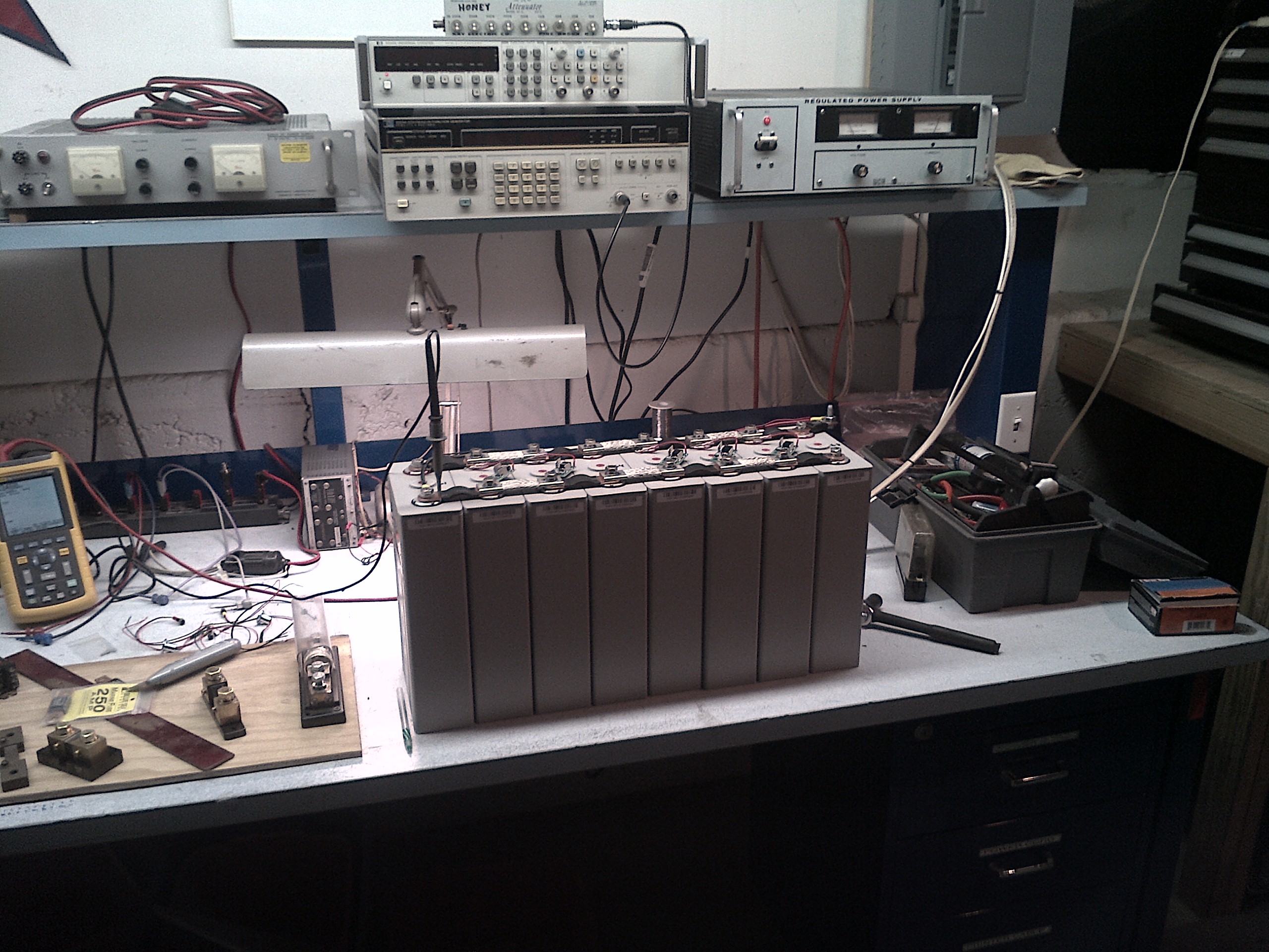
Here is a link to a description of a 1216AH 4P4S battery that Stan assembled for use on Sally and Stan’s powerboat SARISSA in 2024
Below there are links to summary notes and schematics describing the LiFePO4 (aka LFP) battery that Stan assembled for use on Sally and Stan’s Cal 40 Illusion.
Weather and Waves for Offshore Sailors and Navigators
This is an article written by Stan Honey and Ken Campbell on weather for offshore sailors. It was written for a US Sailing book on offshore safety.
Safety Observations 2005-2006 Volvo Ocean Race
This is an article that Stan wrote for the CCA with safety observations about the 2005-2006 Volvo Ocean Race.
Fox Trax Glowing Hockey Puck
Here is an article by Rick Cavallaro describing the history of the development of the Fox Trax glowing hockey puck which was introduced at the Fox Sports broadcast of the 1996 NHL All-Star Game.
Yellow First Down Line, Sportvision
This is a link to an article in IEEE Spectrum summarizing the history of Sportvision and the Yellow First Down Line.
LiveLine
This is a link to an article that Stan Honey and Ken Milnes wrote for IEEE Spectrum describing the LiveLine augmented reality graphics and electronic umpiring system that they developed along with Tim Heidmann, Mark Sheffield, Graeme Winn, and Alistair Green for the 34th America’s Cup.
Vestas Wind
INDEPENDENT REPORT INTO THE STRANDING OF VESTAS WIND (Version 1.2)
This is an Independent Report that was convened by the Volvo Ocean Race following the stranding of the yacht Vestas Wind on 29 November 2014 on the Cargados Carajos Shoals 240 nm north east of Mauritius while competing in the 2014 – 2015 Volvo Ocean Race round the world.
Chris Oxenbould, Stan Honey and Chuck Hawley
31 January 2015
m36616_team-vestas-wind-inquiry-report-released-on-9-march-2015
Grounding and bonding on sailboats
Below is a link to an article that Stan wrote for Practical sailor that was published in the October 15 1996 edition, and has been posted online in the West Marine Advisors ever since. It is also included in the recent Practical Sailor book on marine electrical systems.
The electrical engineering issues of galvanic and electrolytic corrosion, RF grounding, and AC shorepower safety grounding remain the same and the article remains relevant today.
SRI Radar Reflector Study
This is the report from a study on the effectiveness of marine radar reflectors performed by Dick Honey, Stan Honey, Jim Corenman, and Chuck Hawley in September 1995. It was done with the generous cooperation of SRI International in Menlo Park who provided the use of their state-of-the-art radar cross-section measurement range which was normally used to precisely assess the design of aircraft that seek to minimize radar cross-section. Eldon Fernandes, the operator of the SRI RCS range and an employee of SRI, provided invaluable support. The study was originally published by Practical Sailor in September 1995. At the time, Dick Honey was a senior principal scientist at SRI, Stan Honey was a former research engineer at SRI and VP Technology at News Corporation, Chuck Hawley was the technical director for West Marine, and Jim Corenman was a electrical engineer and active cruising sailor.
The physics of electromagnetics remain the same and the conclusions of the report are still accurate today. Many of the radar reflectors tested are still popular. An octahedral radar reflector such as the Davis or Plastimo, in the double catch-rain position, remain a reasonable choice. The common Mobri radar reflectors are essentially invisible to radar on sailboats that heel. None of the passive radar reflectors are more than marginally useful offshore where ships might only be using S-band radars.
Finally, sailors should remember that the small boat is both better able and more highly motivated to detect and avoid a collision with a ship than vice versa. A small boat radar can detect a ship at 12 miles by radar whereas a ship’s radar can only see a sailboat at 3-4 miles.
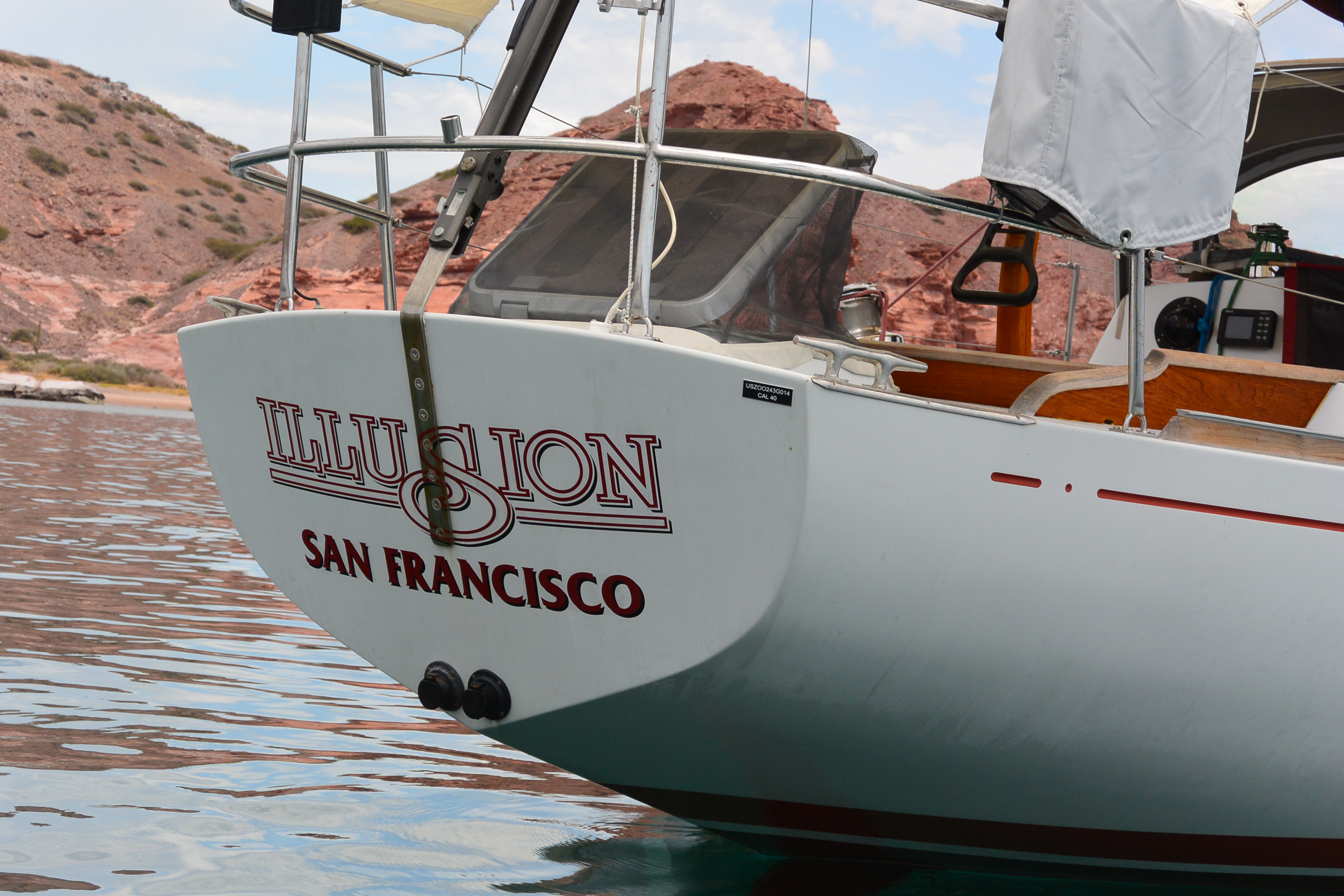
When Sally and I bought Illusion in 1988, she was a wreck, having sat out of the water for 7 years with multiple bullet holes in the hull, no engine, broken rudder-tube, and part-time homeless folks living onboard. After a very busy two years with lots of help from Ron Moore, Bob Pearce, Alan Wirtanan, and Hap, we first raced Illusion in the 1990 Pacific Cup.
We didn’t know it when we bought her, but Illusion turned out to be a well-known New York Yacht Club Cal40, originally owned by Bus Mosbacher and Vince Monte-Sano. There is a half-hull of Illusion in the NYYC model room apparently because Mosbacher/Monte-Sano won the NYYC annual regatta or cruise. Bizzy Monte-Sano visited Illusion when he was in San Francisco a few years ago and filled us in on lots of stories. Bus Mosbacher skippered Weatherly, sail number 17, in the America’s Cup, so Illusion’s original sail number was 1700.
We did the normal upgrades to Illusion. New Ballenger rig/boom, new engine, glassed the hull/deck joint, new rudder, faired hull/keel, new LPU deck/hull, new wiring, new deck gear, new chainplates, new electronics, and new sails. The only original sail that we occasionally use is a Ratsey and Lapthorne spinnaker staysail. Illusion remains a “class” Cal40 with all original dimensions.
We bought Illusion in 1988 intending to go cruising, but old habits die hard so we mostly raced. We’ve raced Illusion to Hawaii 5 times. I set the singlehanded Transpac record in 1994. Sally and I won the Pacific Cup overall fleet in 1996, sailing doublehanded. We won class in the Transpac and 3rd overall in 2003 sailing with Cal40 legends Jon Andron and Skip Allan on our four person crew. Sally raced Illusion with a four woman crew in the 2005 Transpac and got 2nd in class. We’ve also won the Northern California inshore YRA series and the offshore OYRA series, and have competed in countless Farallon Races, singlehanded, doublehanded, and crewed, and won our share.
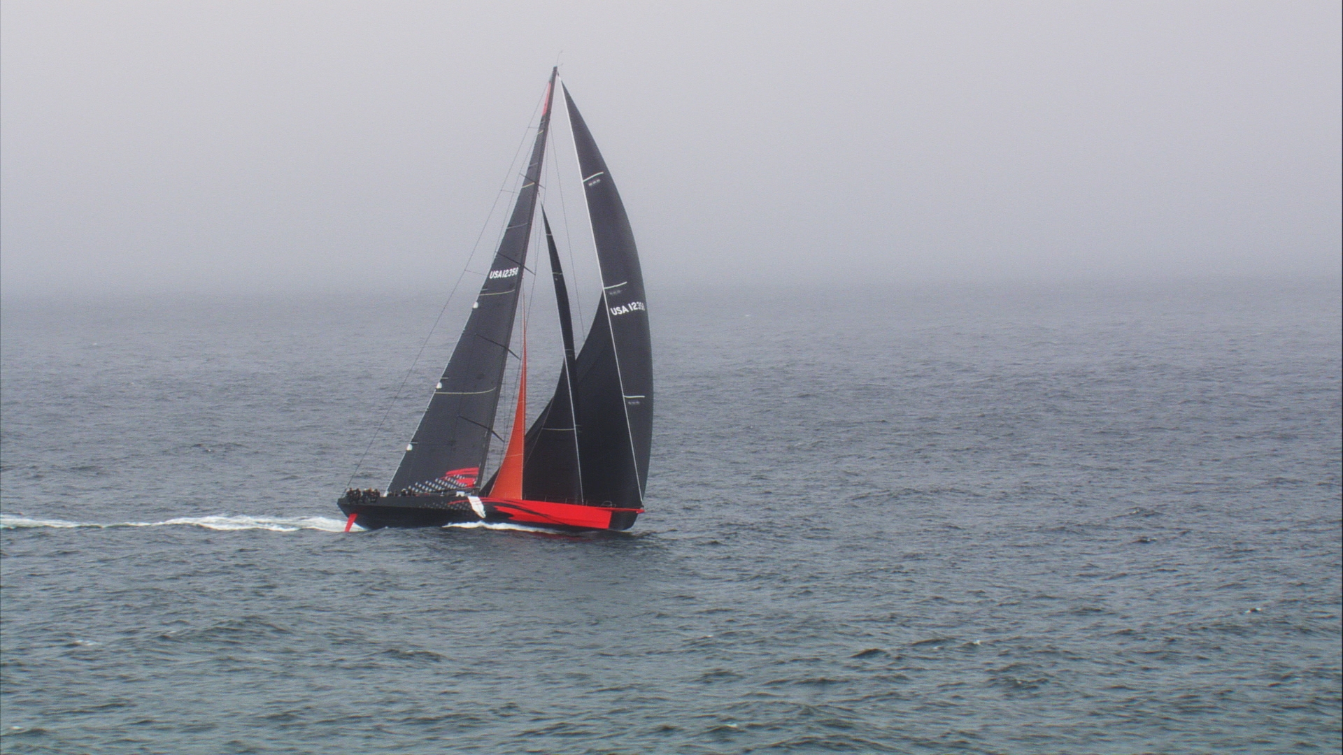
We’ve found that Illusion is a terrific boat to race shorthanded, mostly because the Cal 40 has such “nice manners”. It steers terrifically under autopilot. That results in part from the fact that the Cal 40 doesn’t have a wide stern, and so doesn’t try to turn whenever it heels or rolls. Of course Cal40’s are legendary in their ability to carry sail downwind, as seen in the photos below. In all of our Hawaii Races, shorthanded or crewed, we’ve never had to douse the kite for control, and the autopilot could steer at any time with the kite up.
In 2014 we finally decided to give cruising a try and sailed Illusion to Mexico. We spent two years cruising Illusion in the Sea of Cortez and on the Gold Coast of mainland Mexico. Another year was spent cruising Central America to Panama. Yet another year in the Western Caribbean including stops in Boco del Toro, the San Blas Islands, Providencia, Grand Cayman, Cuba and finally Key West. We’re on our way to New England to resume old habits and race in the 2020 Newport Bermuda Race. Sally and I were not sure that we’d enjoy cruising but we’ve had a terrific time. Part of the reason is that cruising is stress-free in a boat that we’ve raced so much doublehanded. The cruising community that we’ve run across thinks that we’re nuts because we’re delighted to sail in lots of breeze, even upwind.
Below are posts describing various upgrades we’ve made to Illusion. But first some photos…
Stan and Sally

Illusion finishing 2003 Transpac. 1st in class, 3rd in fleet. Crew: Sally Honey, Stan Honey, Skip Allan, Jon Andron

C40 Illusion 2001 SF Lightship Race 1st in class all girl crew

C40IllusionFinishing 2003 Transpac

Illusion 1993 Doublehanded Farallones Race 1st in class passing under Golden Gate Bridge returning from the Farallones.
Safety at Sea book
Click on the link below to retrieve a copy of an unpublished book edited by Sally on Safety at Sea.
Safety At Sea Core Topics Handbook15
ETAK files and photos
Popular Science Article on ETAK, July 1985
Paper presented at the Royal Institute of Navigation meeting in York 1985
ETAK’s initial product brochure 1985
technical paper on ETAK Map Matching Augmented Dead Reckoning 1986
The Forgotten Story of Etak’s Amazing 1985 Car Navigation System Edwards 2015
Etak software article in the C Journal by Ken Milnes and George Loughmiller


Early engineering group LtoR: Terry Obrien, Marv White, Walt Zavoli, Alan Phillips, Jamie Buxton, Ken Milnes, Stan Honey, Jerry Russell.


