We installed a Yanmar 3GM30FV. Bob Pearce did the installation, and did an outstanding job. We use the 2.61 reduction gear, the built in V-drive, and an 18 inch two-blade “classic” max prop with the pointy tip at the hub. Cal40’s originally came with 1 1/4 inch shafts that were machined to 1 inch at the prop to allow a smaller hub. Our shaft is 1 1/4 the entire way so we have the larger max prop hub. That makes the bearings in the hub larger so that they are very long-wearing and we’ve never had the play in the blades increase.
The propeller rpm is about 1000 at our cruising rpm with our transmission, so the propeller tip speed is about 80 ft/sec. 95 is about the top limit for tip speed for a Max Prop because it has no twist in the blades and the tips can cavitate if they run too fast. It is very efficient with the large prop. We’ve tinkered with the pitch and ended up with 20 deg, which is equivalent to about 12.4 inch. That has us powering at about 6.25 knots at 2600 rpm, using about 2/3 gallon per hour. It is slightly “over-propped” at that pitch, so wide open the engine only gets to about 3300 rpm.
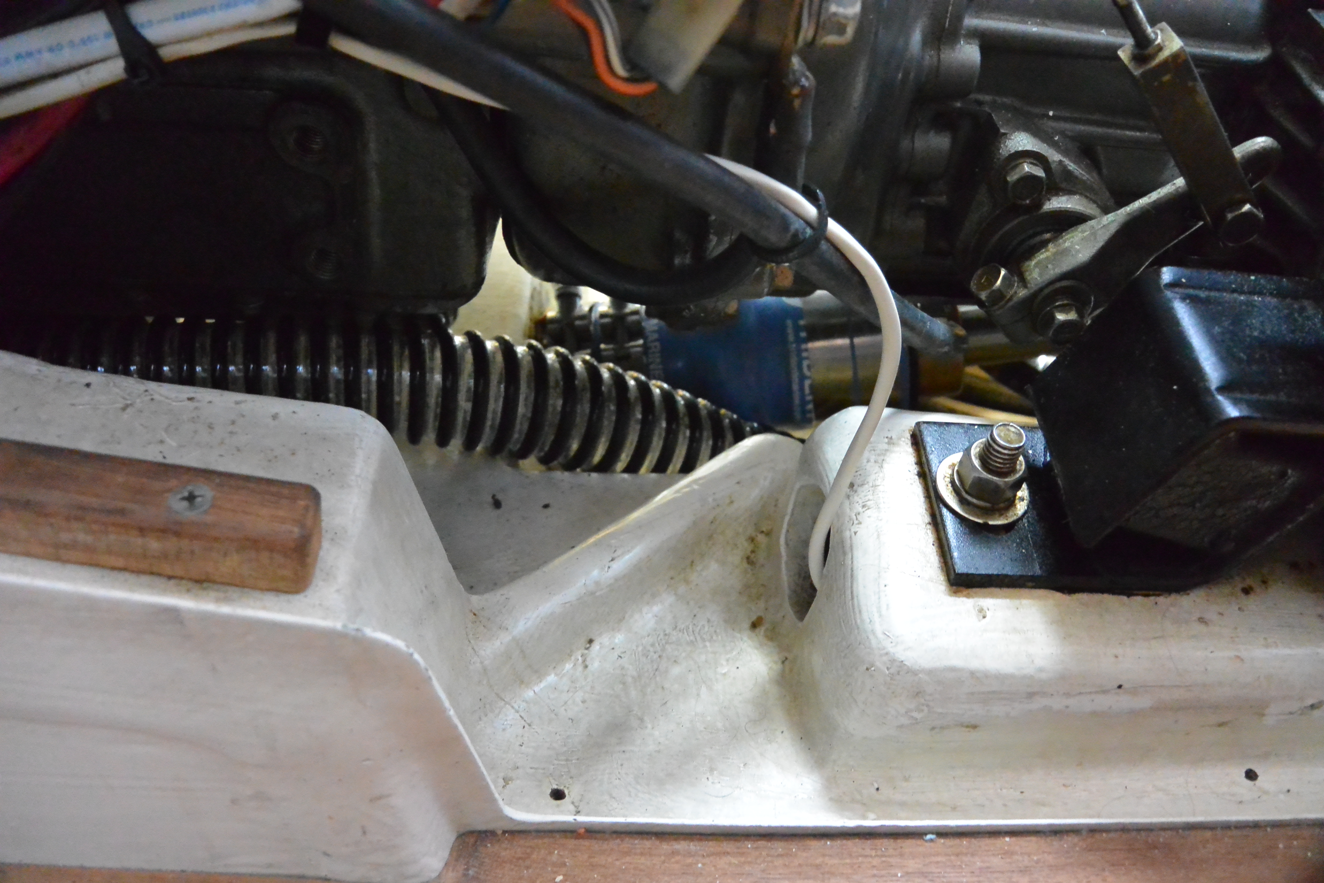
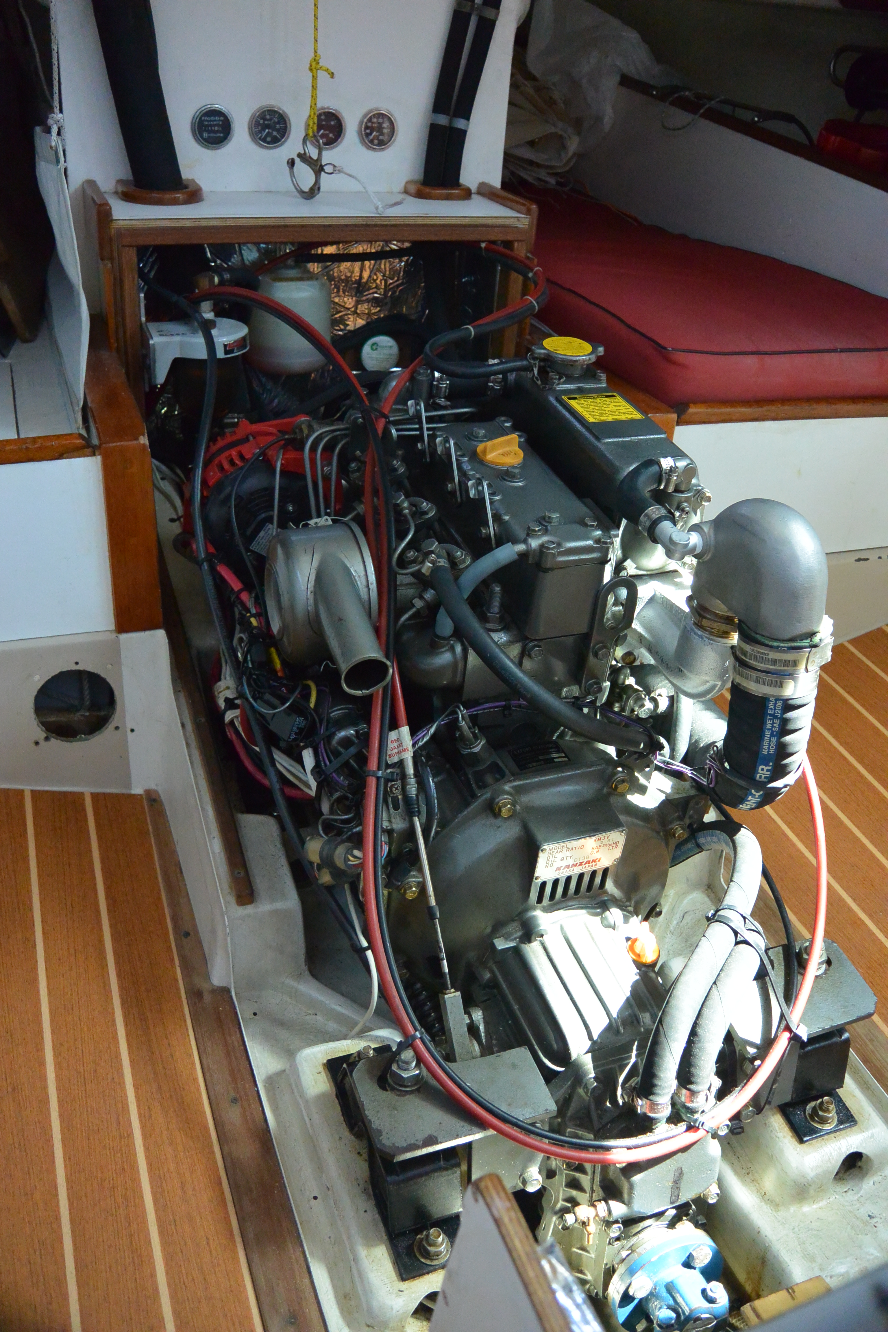
We use the stiffer Yanmar 150 mounts, and use a Norscot stuffing box, which we’ve had great luck with. It’s great to never have ANY saltwater or mist under the engine where the stuffing box is on a V-drive.
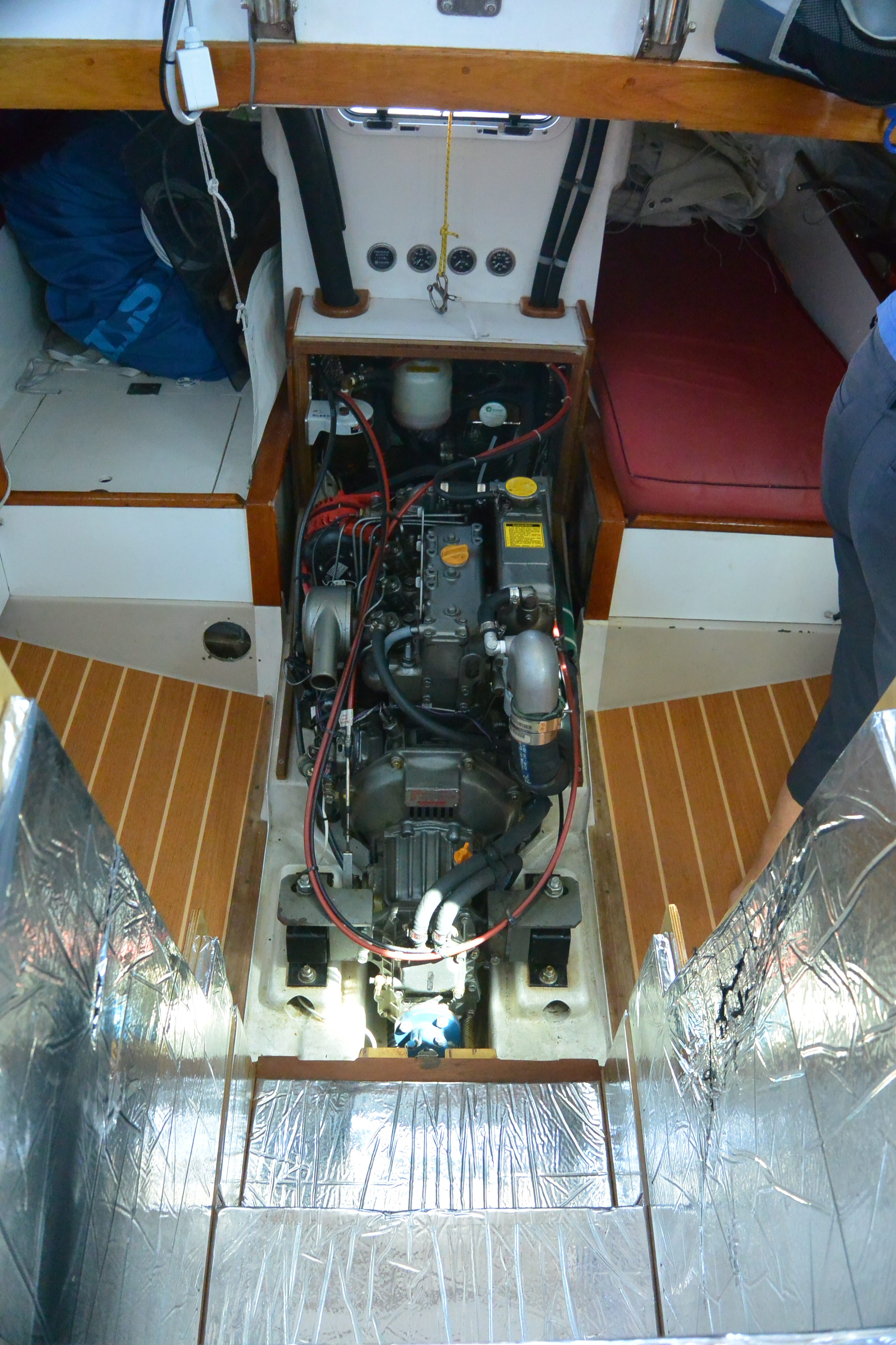
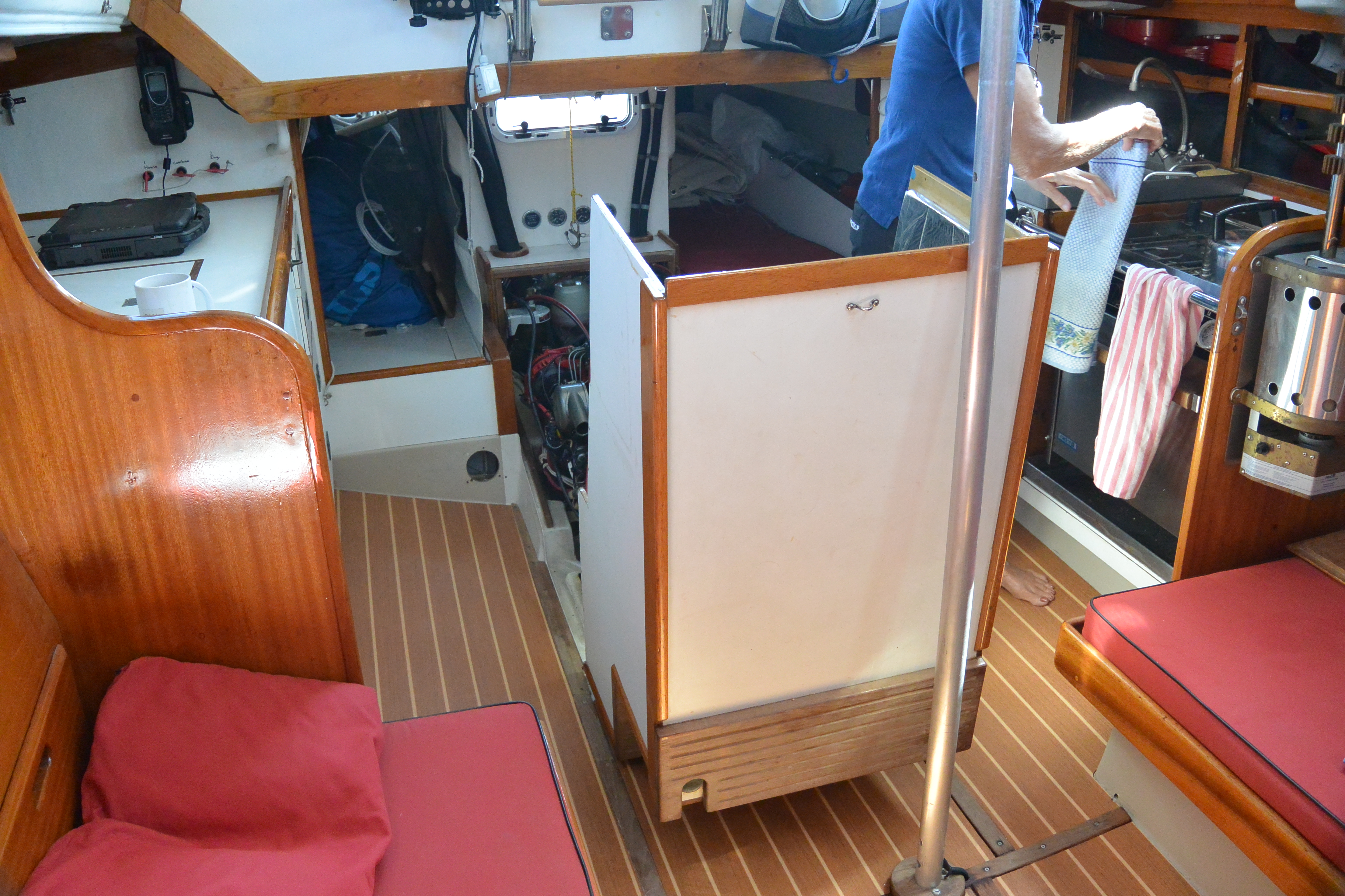
When we bought Illusion, there was no engine and the Walthers V-drive was ruined. We found that if we used an engine with a built-in V-drive, and moved the engine forward and down in the boat, it could perfectly connect to the existing shaft location. Of course we had to build new mounts. Moving the engine forward, down, and saving the weight of the Walthers V-drive were bonuses of this approach. Using an engine with an integrated V-drive also allowed us to move the forward edge of the engine box aft, so we gained room on both ends. Moving the engine forward allowed us to put in a bulkhead at the forward end of the cockpit well, i.e. the aft edge of the bridge deck that runs down to the hull. This bulkhead stiffed the boat and carries our traveler load.
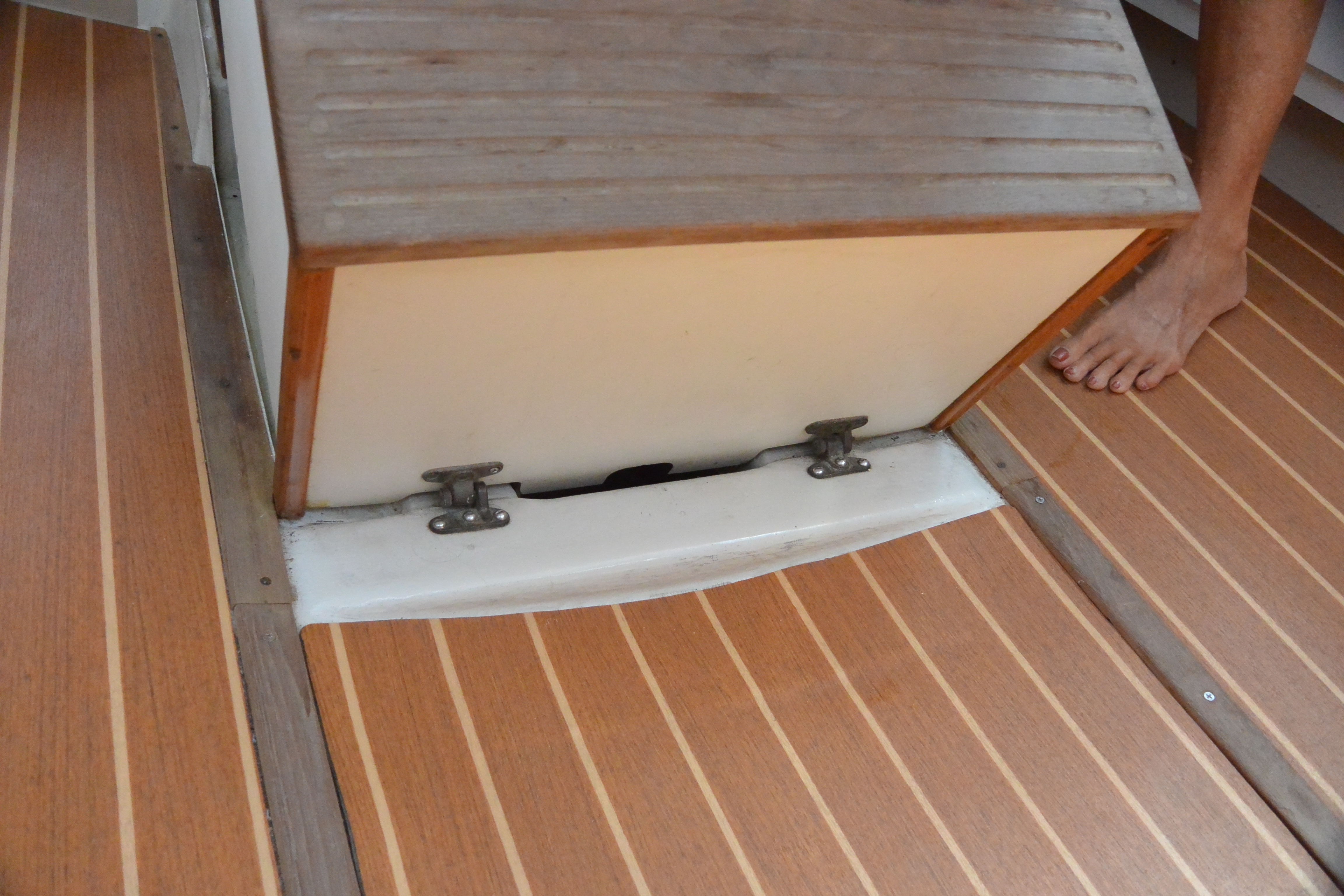
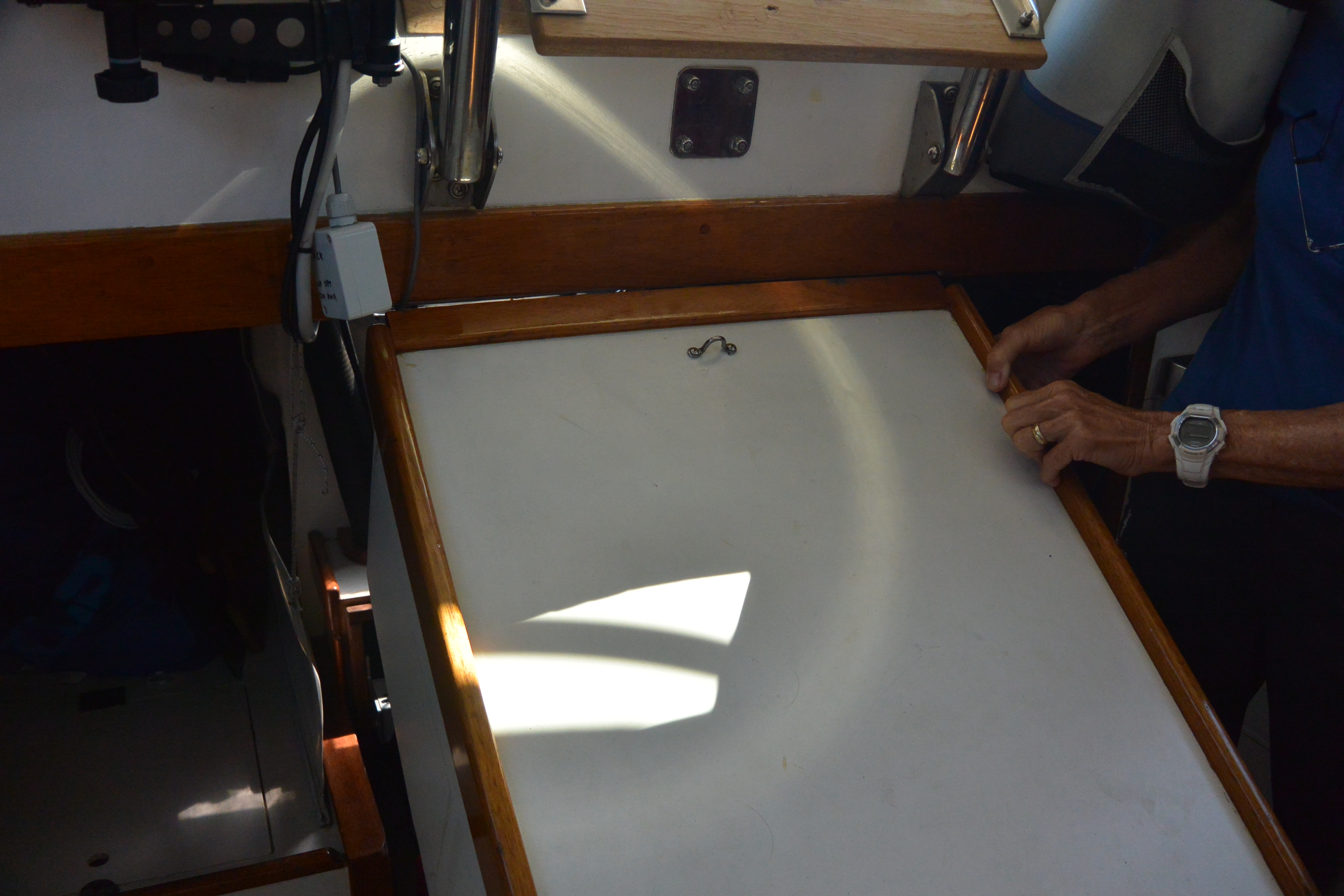
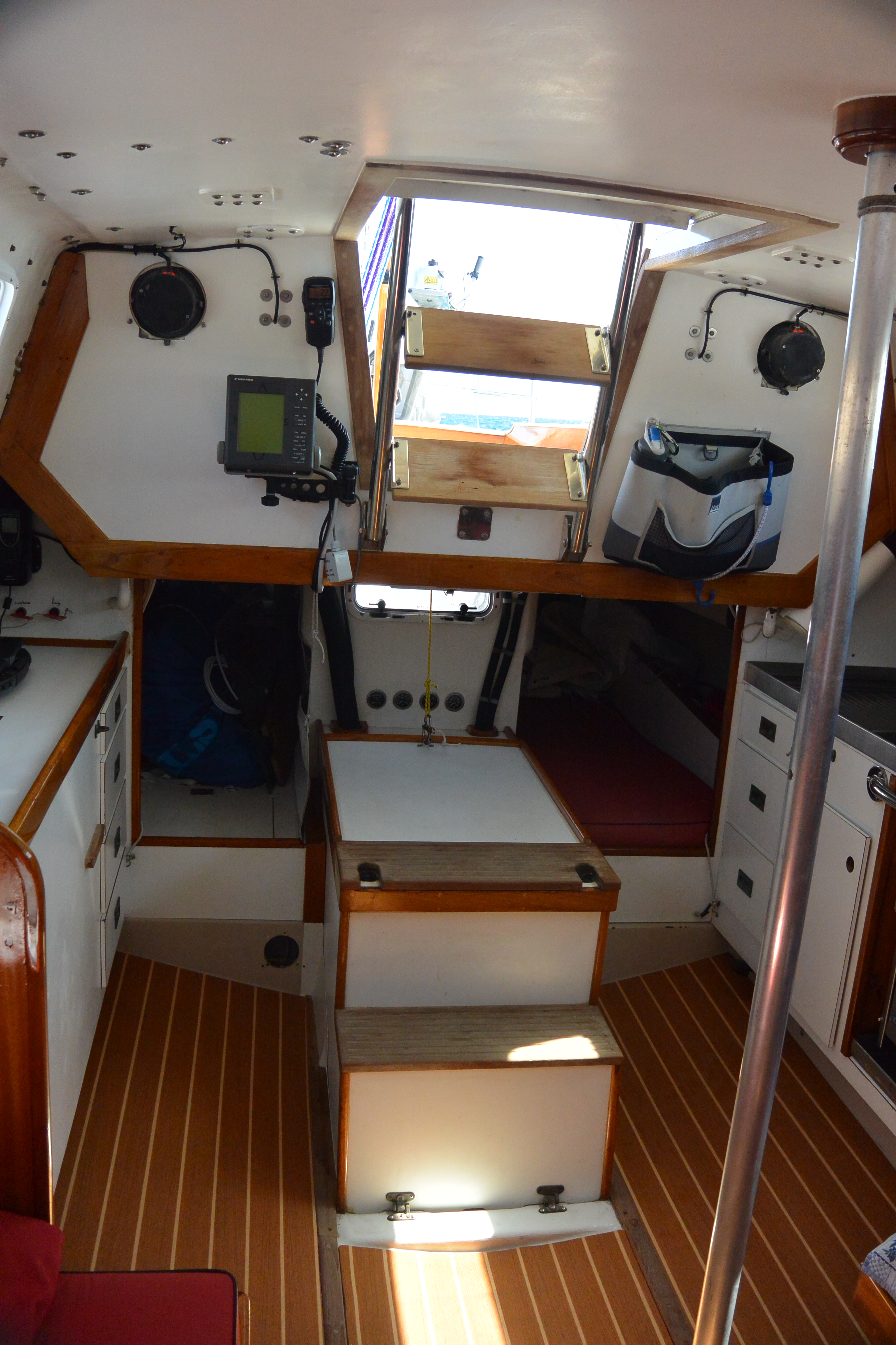
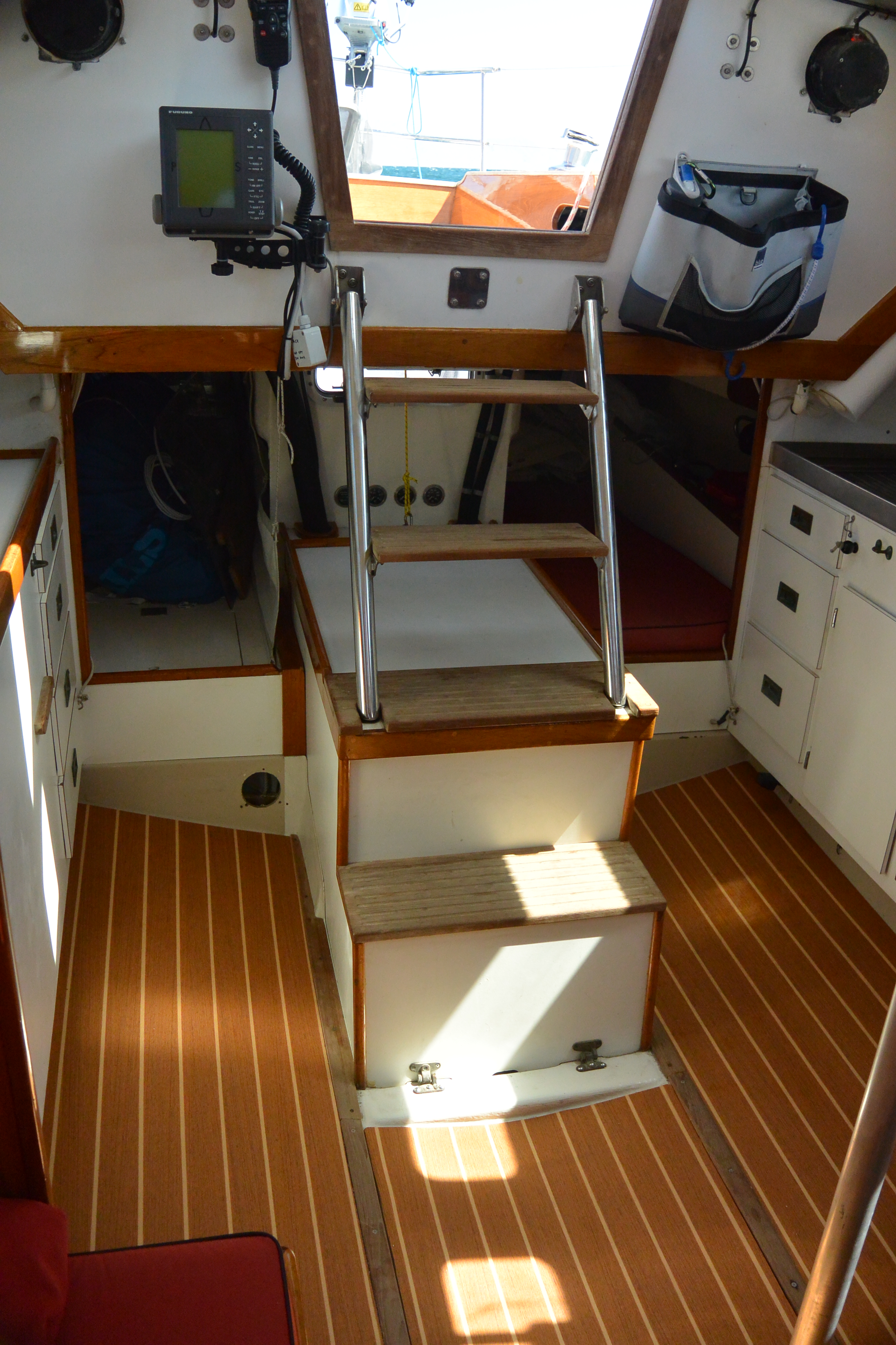
The engine box pivots on two removable spring-pin hinges on its forward lower edge. We designed the engine box so that when it pivots up and forward, it just clears the wood trim under the companionway. The box is all one piece so that water that comes down the companionway never can get to the engine, it just flows around the engine box then onto the cabin floor, then into the keel well. If we need to do serious work on the engine we remove the box by pulling the two hinge pins and set the box on a settee.
The box is shaped to be used as the two bottom steps of the companionway ladder. The first step just clears the transmission/v-drive, the second step clears the top of the exhaust mixing-U, and then we have two more steps that are part of a SS ladder that pivots down from the companionway.
It’s hard to describe but the photos might make it clear.
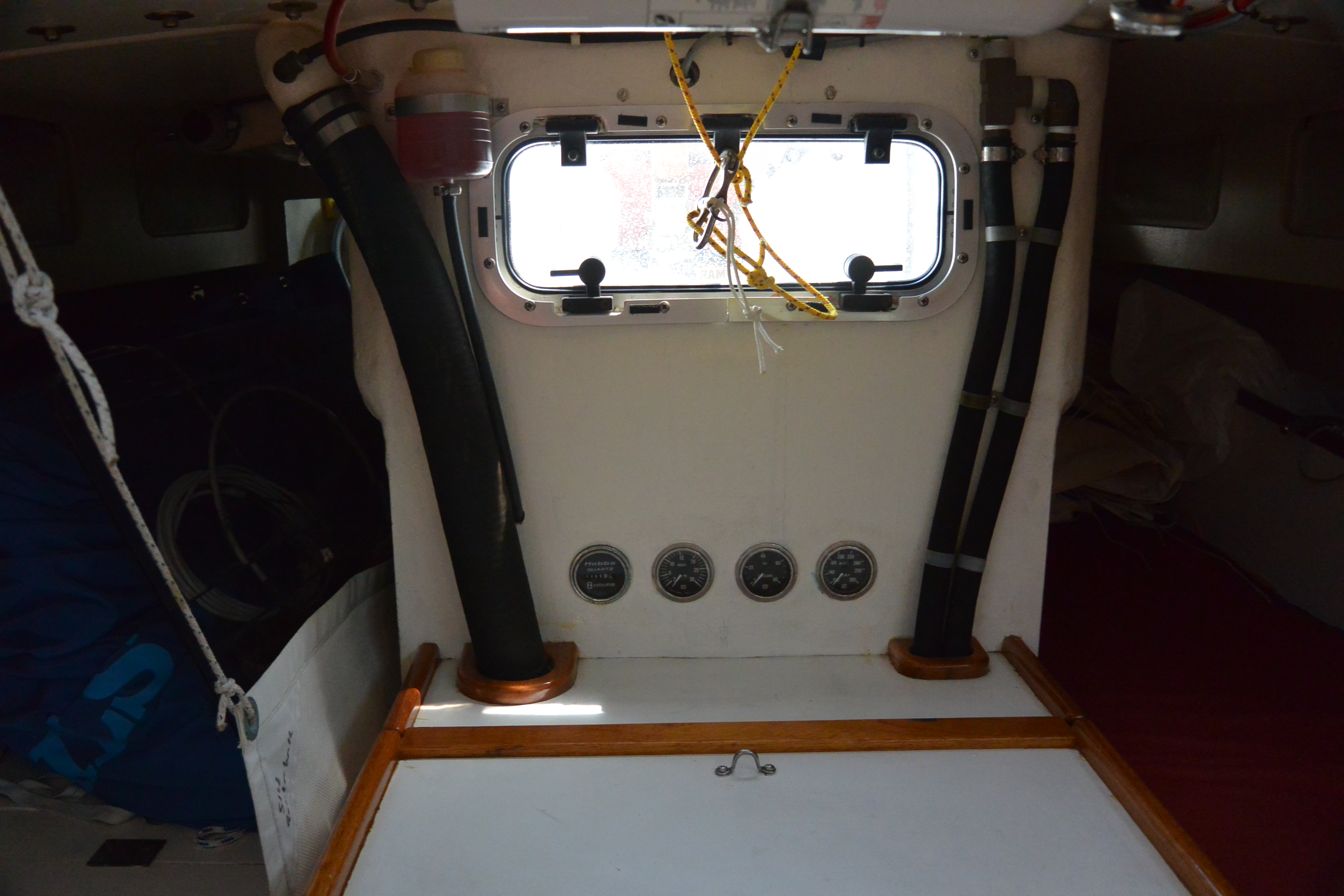
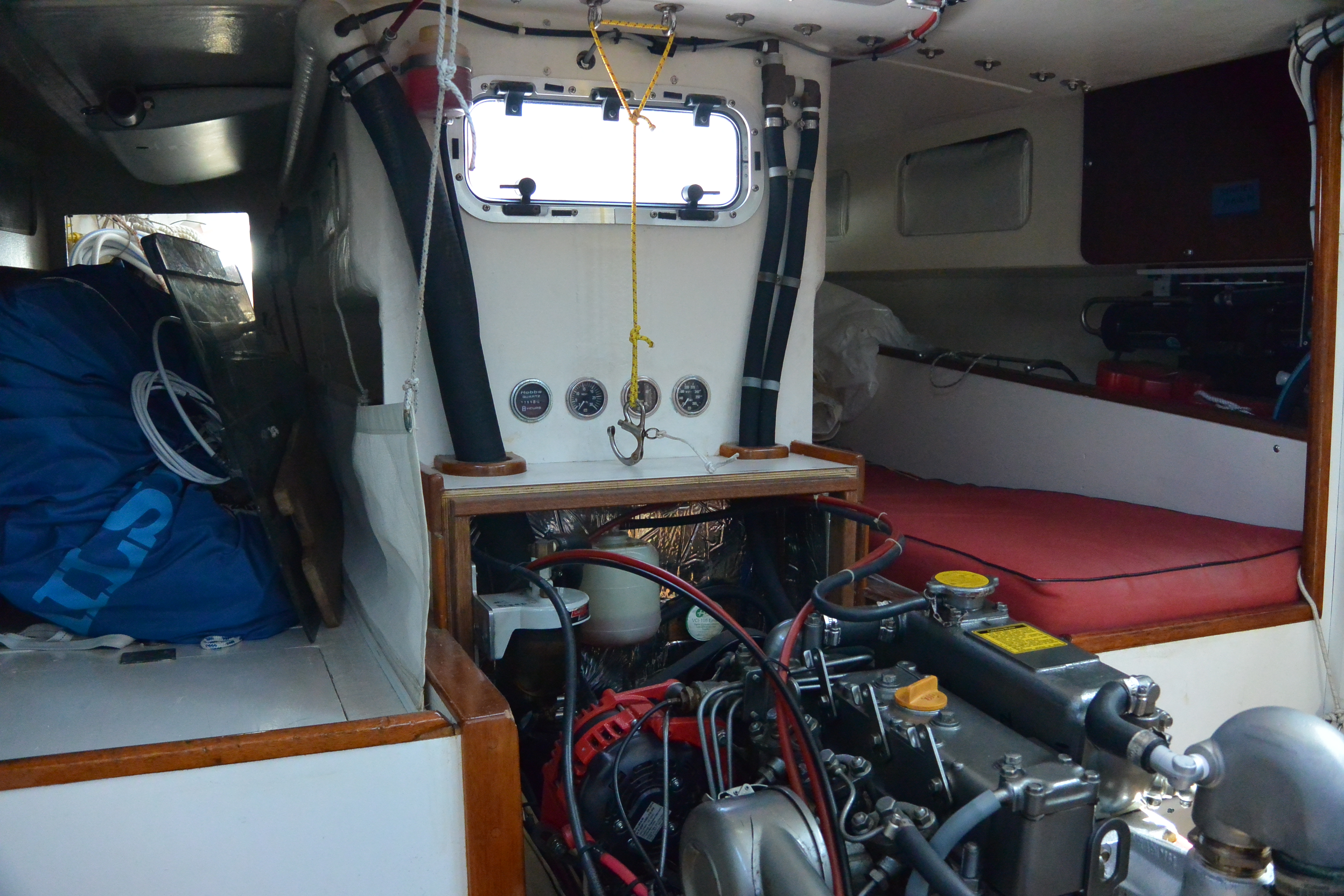
The gauges above the engine box are engine-hours, oil pressure, coolant temperature, and fuel vacuum. They are all mechanical gauges except of course for the hourmeter.
The waterlift muffler is aft of the engine, against the new bulkhead that is at the forward side of the cockpit well. The exhaust goes up from the waterlift muffler to just under the bridge deck, and then goes aft via a fiberglass exhaust tube, at a slight angle down, all the way to the transom.
We replaced the standard Yanmar-Hitachi alternator with a Balmar, and upgraded to a serpentine belt. It is terrific to never have any belt dust.