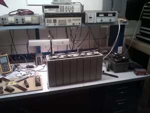
Here is a link to a description of a 1216AH 4P4S battery that Stan assembled for use on Sally and Stan’s powerboat SARISSA in 2024
Below there are links to summary notes and schematics describing the LiFePO4 (aka LFP) battery that Stan assembled for use on Sally and Stan’s Cal 40 Illusion.

Stan,
Really appreciate that you shared your LFP battery work. Years ago, 1996 or 1997 we met and you introduced me to Sailmail. Beth and I used it for 3 years from Mexico to NZ with great success. The old boat name was “Cygnus”. We were berthed in Alameda before we left.
Anyway,
I’m installing a LFP battery bank and wondered if you’ve got a circuit diagram that you refered to when you were talking about using the P-FET to trigger the BS 7712. I’ve got a 24V pack and am learning a bit about MOSFET’s to see if I can use the same parts at 24V. So far I am uncertain. Also there are a few unrecognizable bits in your bud box that I wondered what they were.
Once again great stuff and thank you so much for sharing.
Warmest Regards
John Pohle
“Elizabeth Anne”
Very comprehensive description of your LiFePO4 system. Thank you.
Hi John,
There is a scan of the battery schematic attached. It is just a rough hand drawing. The P-FET that I used would work fine for 24v. There was a typo in the write up and schematic on the part number of the P-FET. I used a STP10P6F6 P-channel Mosfet which is available from DigiKey. That P-FET is rated for 60v so would work fine for 24v. I fixed the typos in the write up and on the hand drawn schematic.
Cheers,
Stan
Hi Stan,
We met briefly at a talk you gave about your Americas Cup technology in San Francisco.
Jerry Keefe forwarded your Lithium write-up to me. I have a self-installed 800ah CALB system two paralleled 400 Packs which can be isolated. My boat is a cat so I have 2 balmar setups with duocharge for start batteries, and centerfielder.
I get a charging alarm as the regulator goes to float. Per Balmar, the battery voltage stays high after the switch from Absorption. This is because the regulator drops field voltage drops to zero which creates the alarm state. I have been fooling around with the various voltages moving the voltages towards my float of 13.6.
Per my CALB document, I am supposed to charge at 14.4 and float at 13.6. I view the absorption phase as an extension of the bulk phase so I stay at 14.4 on my shore power charger. Your charge voltages are obviously lower… Why are you doing that, or conversely why should I? I have been closing the gap on my float by reducing the bulk and absorption closer to the 13.6 float to eliminate he alarm. Balmar suggested I solve the problem by increasing the float voltage. I would never do that because it’s out of range per the battery manufacturer
I am starting to think that any voltage between 14.4 and 13.6 would be adequate because of the lithium charge profile. I’m thinking even if I set the bulk to 13.6 my charging amps would only be slightly lower.
Per Balmar (they know its lithium) my belt manager is set to 3.
I am also interested in your thoughts on frequent exposure of the pack to the higher bulk voltage. On shore power my Mastervolt goes to bulk every so often (two weeks I think) my solar 800watts with two MPPT controllers start at bulk every day and yet while on shore power the pack is staying charged all the time. My pack has been installed for about 2 years mostly on shore power. The solar is six months old. WE are now long term cruising so lots of anchor time. Because the pack is fully charged the bulk phase is very short
I hit my cells with an IR temp gauge and have never measured anything over ambient even after an hour of charging.
I did have one defective cell that began to rapidly loose voltage about six months in.. Per CALB this happens. I was able to balance the new cell with the 3 older cells using your method and they are maintaining their balance after a year or so.
I am using Mastervolt, Balmar and Manzanita Micro systems for BMS.
Thanks for your thoughts.
Michael Britt
Hi Michael,
I selected 13.8 for bulk as a result of some experiments. With the MC-614 regulator set up as described, it changes to “absorption” from the 13.8v bulk phase, at about 25 amps of charge current which at that point is dropping very rapidly. I have tried subsequent charge cycles at higher bulk voltages and found that the battery doesn’t accept much charge beyond that. So I ended up picking 13.8v because it gets the battery to 90% charge. Unlike lead chemistry batteries which like to be fully charged to avoid sulfation, my impression is that there are zero advantages to fully charging a LFP battery other than the small amount of additional storage. The 13.6v absorption is 0.2v lower just to pass through that unnecessary phase quickly. I use 13.4v for “float” because 13.4v is the resting open circuit voltage of the battery, so with the “float” set at 13.4v, charging stops.
I never charge in the slip. I instead leave the LFP battery completely disconnected at 50% charge and then run the boat off of a regulated DC power supply directly from shore power. This has the interesting benefit that if somebody kicks the power cord out, you find out about it right away.
cheers,
Stan